What are Relays?
A relay is a type of electromechanical switch that has a variety of uses in home automation, DIY projects, IoT projects, automobiles like bikes, cars, trucks, etc., and industrial applications.
Relays are used where you want to turn ON/OFF devices with a low DC voltage. To understand this, let’s take an example of turning ON/OFF a 220V bulb. In your home, you must have seen a switch that is used to turn ON/OFF a bulb. Now, suppose you want to turn the ON/OFF bulb with the help of an Arduino, what will you do? You already know an Arduino Board can’t power a 220V bulb.
In this case, we will use a relay. The Arduino will send an ON/OFF signal to the relay and the relay will turn ON/OFF the bulb based on the signal given to the relay.
Working of a relay?
Here, we will discuss the working of an SPST relay that has 5 pins.
Let us take an example of turning ON/OFF a 220V light bulb with the help of Arduino.
You already know that an Arduino board can only output a maximum of 5 volts. Which is way less than the required voltage of the bulb.
So, in this case, we have to use some kind of module that can convert the 5 volts to 220 volts. The most suitable module for such types of applications is the relay module.
Arduino will give an input signal to the relay either it is Logic ‘0’ or Logic’1′ depending upon the type of relay. And the relay will give 220 v to the light bulb.
Pin diagram of a 1-Channel relay module
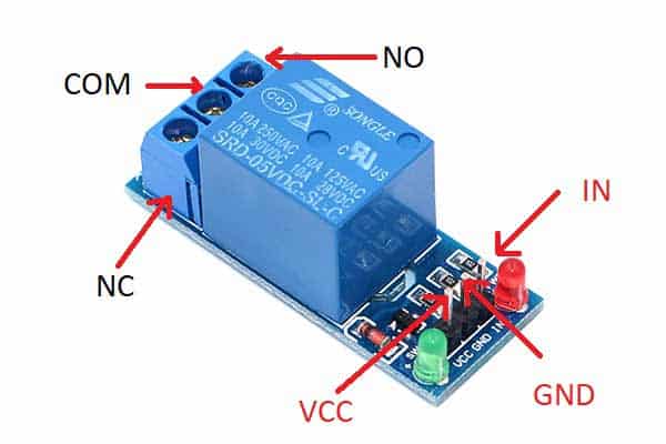
The relay module consists of three pins. The first one is Vcc, then the ground and the last one is an Input pin where you will give an input signal.
On the other side, there are three terminals where you will connect your device. The first terminal is NO which means normally open terminal, the second one is COM which means common terminal and the last one is NC which means Normally closed terminal.
Two LEDs are also present on module one for indicating the power status. When you give power to the module the green LED will light up.
The other LED is for indicating the signal. If you give a signal to the input pin of the relay module the red LED will light up.
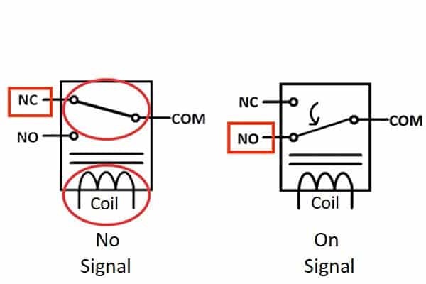
Now, I will discuss how these three terminals NO, NC, and COM work.
The relay consists of a coil and a moveable magnetic latch. This latch is by default connected to the NC pin and when you give a signal to the coil the latch gets connected to the NO pin.
1-Channel Relay Working
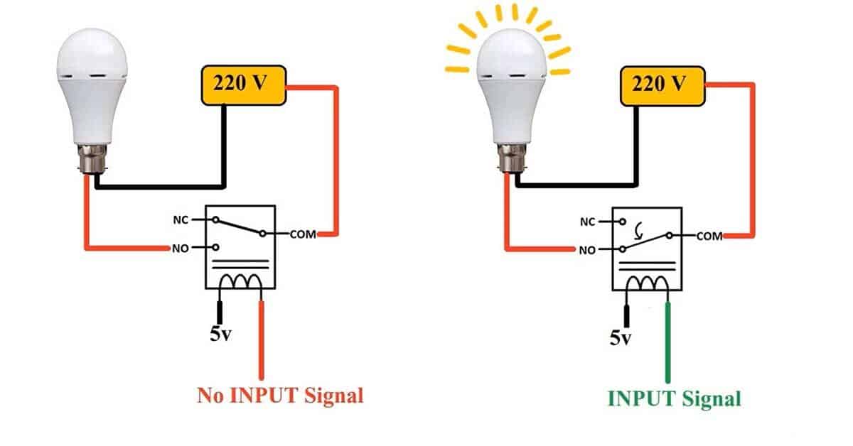
This circuit represents how you should connect a device to the relay. In the circuit, I have connected one end of the coil to the VCC and another end is left for Signal. This is a logic 0 relay which means you have to give a logic 0 signal to turn on the relay.
One wire of the bulb is directly connected to the 220 volts and the other wire of the bulb is connected to the NO pin. And the com pin of the relay is connected to the 220 v.
When there is no signal. The COM pin is connected to the NC pin. So, the NC pin will get 220 volts. But the bulb is connected to NO pin, the bulb will not turn ON.
When you give a signal to the relay, the latch will move and get connected to the NO pin. The circuit will be completed and the bulb will turn ON.
Specifications of 1-Channel Relay Module
- Input Signal Voltage: 5V
- Maximum voltage and current for connecting a DC device: 30VDC 10A
- Maximum voltage and current for connecting an AC device: 250VAC 10A 50HZ
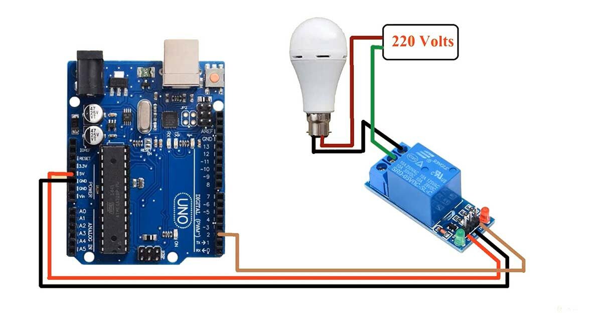
Circuit diagram of Interfacing 1-Channel Relay module with Arduino
Pin connection of MQ9 Gas Sensor with Arduino
- Connect the VCC pin of the relay module to the 5V pin of the Arduino UNO board.
- Connect the GND pin of the relay module to the GND pin of the Arduino UNO board.
- Connect the Input pin of the relay module to the D2 pin of the Arduino UNO board.
*********************Warning*********************
All NO, NC, and COM terminals are exposed to the air. You might touch them while working with the relay module. Avoid touching them with a bare hand. Be careful while using the relay with 220V. Mishandling of such a high voltage can lead to injury or even death.
- Connect the COM terminal of the relay module to the 220V Live wire.
- Connect the NO terminal of the relay module to the Bulb.
- Connect the remaining terminal of the bulb to the 220V Neutral Wire
Arduino code for interfacing Reed Switch with Arduino
int relayPin=2;
void setup()
{
  pinMode(relayPin,OUTPUT);
 }
void loop()
{
  //Turn ON relay
digitalWrite(relayPin,HIGH);

//Turn OFF relay
//digitalWrite(relayPin,LOW);
}
Reed switch with Arduino code working
int relayPin=2;Create one variable named relayPin to store the pin number of the Arduino board pin where you have connected the Input pin of the relay module. In my case, I have connected the Input pin of the relay module to the D2 pin of the Arduino UNO board.
void setup()
{
  pinMode(relayPin,INPUT);
 }
Use the pinMode() function to set the relayPin as OUTPUT. The Arduino will use this pin to send ON/OFF signal to the relay module.
void loop()
{
  //Turn ON relay
digitalWrite(relayPin,HIGH);

//Turn OFF relay
//digitalWrite(relayPin,LOW);
}
Use digitalWrite() command to turn ON/OFF the relay.