16×2 Liquid Crystal Display (LCD): An Overview
The 16×2 Liquid Crystal Display (LCD) is a popular and widely used display device that is commonly used in various DIY projects, hobby electronics, and even commercial products. It is an inexpensive and simple display that is ideal for beginners and experienced makers alike.
A 16×2 LCD consists of two rows of 16 characters each and is powered by a simple controller that interprets commands from an external device (such as an Arduino board) and displays the corresponding text on the screen. The LCD uses liquid crystal technology to create the characters and has a backlight to make them visible in low-light conditions.
One of the key advantages of 16×2 LCDs is their simplicity and ease of use. They are relatively cheap and widely available, making them a popular choice for hobbyists and students. Additionally, they are compatible with a variety of microcontrollers and can be easily interfaced with an Arduino board using a simple library and a few jumper wires.
Pin Diagram of 16×2 LCD
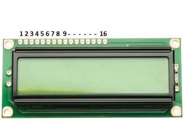
The 16×2 LCD has a total of 16 pins, arranged in two rows of 8 pins each. The pins are typically labelled as follows:
- GND (Ground)
- VCC (Power Supply)
- V0 (Contrast Control)
- RS (Register Select)
- RW (Read/Write)
- E (Enable)
- D0 to D7 (Data Pins)
Here is a brief description of each pin:
-
GND (Ground): This pin is connected to the ground of the circuit.
-
VCC (Power Supply): This pin is connected to the power supply of the circuit, typically 5V.
-
V0 (Contrast Control): This pin is used to adjust the contrast of the display. It is connected to a potentiometer to allow for fine-tuning of the display’s contrast.
-
RS (Register Select): This pin is used to select either the data register or the instruction register. When RS is set to low (0), the data is interpreted as an instruction; when RS is set to high (1), the data is interpreted as display data.
-
RW (Read/Write): This pin is used to select the read or write mode. When RW is set to low (0), the data is written to the display; when RW is set to high (1), the data is read from the display.
-
E (Enable): This pin is used to enable or disable the display. When E is set to high (1), the display is enabled; when E is set to low (0), the display is disabled.
-
D0 to D7 (Data Pins): These 8 pins are used to send data to the display. The data is sent in parallel using these 8 pins, allowing the display to be updated quickly.
Note that the pin configuration may vary slightly between different 16×2 LCD models, so it’s important to check the datasheet of your specific LCD before making connections.
Specifications of 16×2 LCD
-
Display Type: The 16×2 LCD is a character-based display that uses liquid crystal technology to display text and symbols.
-
Display Size: The display is 16 characters wide and 2 rows tall, hence the name 16×2 LCD.
-
Character Size: The size of the characters displayed on the 16×2 LCD is typically 5×8 dots or 5×10 dots.
-
Resolution: The resolution of the 16×2 LCD is typically 80×8 or 160×2.
-
Operating Voltage: The operating voltage of the 16×2 LCD is typically 5V DC.
-
Interface: The 16×2 LCD can be interfaced with various microcontrollers, including the Arduino, through a simple 4-bit or 8-bit interface.
-
Operating Temperature: The operating temperature of the 16×2 LCD is typically between 0°C and 50°C.
-
Power Consumption: The power consumption of the 16×2 LCD is typically low, around a few milliamps.
-
Pin Configuration: The 16×2 LCD has a total of 16 pins, including power supply, ground, contrast control, register select, read/write, enable, and data pins.
Interfacing 16×2 LCD with Arduino
Materials needed:
- 16×2 LCD
- Arduino board (such as Arduino Uno)
- 10k potentiometer
- Breadboard
- Jumper wires
Circuit Diagram of Interfacing 16X2 LCD with Arduino Board
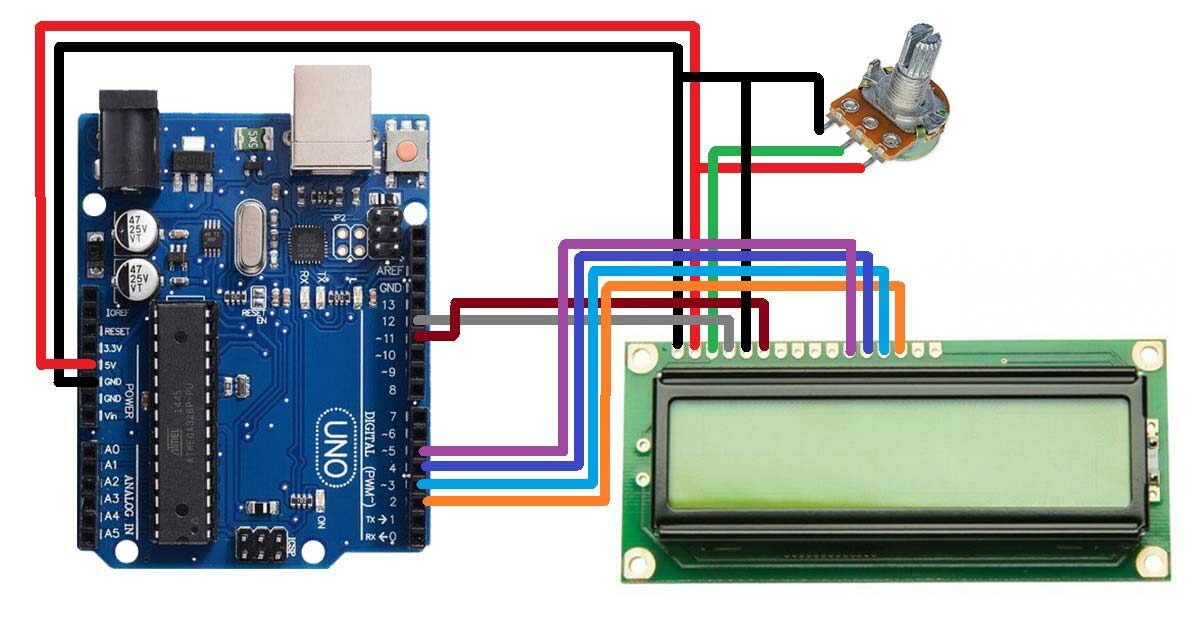
Step 1: Connect the LCD to the Breadboard
Take the 16×2 LCD and place it onto the breadboard. The LCD has two rows of 16 characters each and requires a total of 7 connections to the Arduino board.
- Connect the LCD’s VCC pin to the 5V pin on the Arduino
- Connect the GND pin to one of the GND pins on the Arduino
- Connect the RS (register select) pin to digital pin 12 on the Arduino
- Connect the RW (read/write) pin to GND on the Arduino
- Connect the E (enable) pin to digital pin 11 on the Arduino
- Connect the D4 pin to digital pin 5 on the Arduino
- Connect the D5 pin to digital pin 4 on the Arduino
- Connect the D6 pin to digital pin 3 on the Arduino
- Connect the D7 pin to digital pin 2 on the Arduino
- Connect the contrast pin (Vo) to the middle terminal of the potentiometer
- Connect the other two terminals of the potentiometer are connected to the ground and the 5V pins on the Arduino
Step 2: Install the LiquidCrystal Library
The LiquidCrystal library is a pre-built library that makes it easier to control a 16×2 LCD with the Arduino board. To install it, open the Arduino IDE, go to Sketch > Include Library > LiquidCrystal, and select the LiquidCrystal library.
Step 3: Write the Code
Once the library has been installed, it’s time to write the code. Here is an example code that will display “Hello, World!” on the LCD:
Arduino code for interfacing 16X2 LCD with Arduino Board
#include <LiquidCrystal.h>
LiquidCrystal lcd(12, 11, 5, 4, 3, 2);

void setup() {
  lcd.begin(16, 2);
  lcd.print("Hello, World!");
}

void loop() {
  // Do nothing
}
Step 4: Upload the Code
Once the code has been written, connect the Arduino board to your computer using a USB cable and upload the code to the board. The text “Hello, World!” should be displayed on the LCD.
And that’s it! By following these simple steps, you should be able to interface a 16×2 LCD with an Arduino board in no time. Happy tinkering!