NEO-6M GPS Module: An overview
The NEO-6M GPS module is a compact and cost-effective device designed for use in GPS-based projects. This module is based on the U-Blox NEO-6M GPS chip and provides precise location data to the user. With its low power consumption, compact size, and high accuracy, the NEO-6M GPS module is a popular choice for GPS applications in various fields, such as navigation, location tracking, and autonomous vehicles.
The module has four pins: VCC, GND, RX, and TX. The VCC pin is used to power the module, while the GND pin is connected to the ground. The RX and TX pins are used for serial communication between the module and the microcontroller. The module operates at 3.3V, making it compatible with most microcontrollers, including the popular Arduino board.
The NEO-6M GPS module supports NMEA 0183 and UBX protocols and can provide the user with data such as the current latitude, longitude, altitude, speed, and time. The module is equipped with a built-in ceramic patch antenna and supports up to 22 simultaneous satellite tracking channels.
Pin Diagram of NEO-6M GPS Module
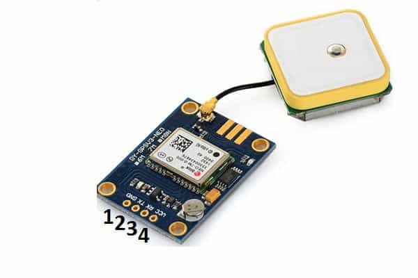
The NEO-6M GPS module typically has four pins:
- GND: This is the ground pin and is connected to the ground of the microcontroller.
- TX: This is the transmit pin and is also used for serial communication.
- RX: This is the receive pin and is used for serial communication between the module and the microcontroller.
- VCC: This is the power supply pin, which is typically connected to 3.3V.
Specifications of NEO-6M GPS Module
- GPS receiver: u-blox NEO-6M
- GPS chipset: u-blox 6
- GPS module frequency: L1, 1575.42 MHz
- C/A code: 1.023 MHz chip rate
- Channels: 50
- Sensitivity: Tracking: -162 dBm, Cold starts: -147 dBm
- Time-To-First-Fix: Cold starts: 26s, Aided starts: 2s
- Accuracy: Position: 2.5m CEP, Velocity: 0.1 m/s
- Protocol: NMEA 0183
- Baud rate: 9600 bps (default), configurable
- Power supply: 3.3V~5V
- Operating temperature: -40°C to +85°C
- Dimensions: 25mm * 25mm * 7mm
Circuit Diagram of interfacing NEO-6M GPS module With Arduino Board
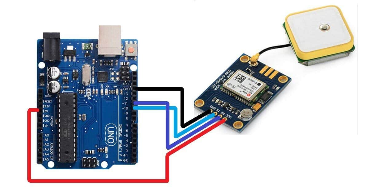
Interfacing the NEO-6M GPS module with an Arduino board is a great way to track the location of your project. In this blog, we’ll show you how to connect the NEO-6M module to an Arduino board and write a simple sketch to read the GPS data.
Materials required:
- Arduino board
- NEO-6M GPS module
- Breadboard
- Jumper wires
Step 1: Connect the NEO-6M module to the breadboard The NEO-6M module has four pins: VCC, GND, RX, and TX.
- Connect the VCC pin to the 3.3V pin on the Arduino board
- Connect the GND pin to the GND of the Arduino board
- Connect the RX pin to the D11 pin of the Arduino Board
- Connect the TX pin to the D10 pin of the Arduino Board
Step 2: Write the sketch Open the Arduino IDE and write the following sketch to read the GPS data:
Arduino Code For Interfacing NEO-6M Module with Arduino Board
#include <SoftwareSerial.h>
SoftwareSerial GPSSerial(10, 11); // RX, TX

void setup() {
  Serial.begin(9600);
  GPSSerial.begin(9600);
}

void loop() {
  while (GPSSerial.available()) {
    Serial.write(GPSSerial.read());
  }
}
Step 3: Upload the sketch to the Arduino board Connect the Arduino board to your computer using a USB cable and upload the sketch to the board.
Step 4: Monitor the GPS data Open the Serial Monitor in the Arduino IDE and set the baud rate to 9600. As soon as the NEO-6M module receives GPS data, you should see a series of NMEA sentences being displayed on the monitor, which represent the GPS location, time, date, speed, and other information.