About this tutorial:
In this tutorial, you will learn how to interface HC-05 with Arduino. The process is the same for connecting other modules that use UART communication. We will use Arduino UNO for this tutorial. You already know that an Arduino UNO board only consists of one UART port(TX & RX). So, you can only interface only one module with an Arduino UNO board that uses UART communication. But what happens when you need to connect more than one module to the Arduino UNO board. We can’t use that same port for all the modules.
For solving this problem we can use a library called softwareSerial. By using this library you can make any of the Arduino UNO board pins as TX and RX and use them for UART communication. To make it easy to understand, I will now interface the HC-05 with the Arduino UNO board.
HC-05 Pin Diagram
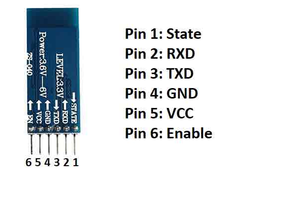
Pin uses
Pin 1: It is status pin. It is used to show the status of the module whether it is connected to some device or not and some other operation like switching between master and slave. This same pin is connected to an onboard LED. That blinks depending upon the different operations.
Pin 2: It is RX(receiver) pin. It is used to receive data from the HC-05. You have to connect this pin to the TX(transmitter) pin of the Arduino UNO board.
Pin 3: It is TX(transmitter) pin. It is used to send data to the HC-05. You have to connect this pin to the RX(receiver) pin of the Arduino UNO board.
Pin 4: It is GND(ground) pin. It is used to connect GND to the HC-05 module.
Pin 5: It is VCC(power) pin. It is used to connect 5V to the HC-05 module.
Pin 6: It is enable pin. It is used to switch between master and slave configuration.
Features of HC-05
- Operating voltage: 3.3-5V
- Operating current: 30mA
- Bluetooth version: v2.0
- Frequency: 2.4GHz
- Modulation: GFSK
- Supported modes: Both master and slave
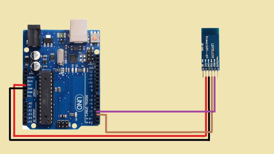
On the Arduino UNO board, there are two pins pin 0 and pin 1 that are used for UART communication. But instead of them we will now make pin 2 and pin 3 as RX and TX using Software Serial library. This library is already included in the Arduino IDE. You do not need to install it.
Circuit diagram for interfacing HC-05 Bluetooth module with Arduino using software Serial
Arduino Code for interfacing HC-05 Bluetooth module with Arduino using software Serial
#include<SoftwareSerial.h>
SoftwareSerial mySerial(2,3);
void setup() {

mySerial.begin(9600);
Serial.begin(9600);
}

void loop() {

if(mySerial.available()>0)
{
  char data=mySerial.read();
  Serial.println(data);
}
}
Arduino Code working
#include<SoftwareSerial.h>
SoftwareSerial mySerial(2,3);
First include the softwareSerial library in your code. Then, define the RX and TX pin using. In bracket first write the RX pin name and after comma write the TX pin name. Here, mySerial is object of SoftwareSerial class. You can use any name instead wo mySerial. But then you have to use that same name everywhere to access all the functions of the SoftwareSerial library.
void setup() {

mySerial.begin(9600);
Serial.begin(9600);
}
In void setup() function, set baud rate to 9600 for pin 2 and 3. Then set the baud rate to 9600 for pin 0 and pin 1. Make sure you Mobile app. is connected to the module.
void loop() {
if(mySerial.available()>0)
{
char data=mySerial.read();
Serial.println(data);
}
}
In void loop(), we will write the code to receive data from the bluetooth module.