About this project and it’s working
In this tutorial, you will learn how to make a home security system. This system will consist of a fire and smoke monitoring system, an LPG gas leakage system, and a water leakage system.
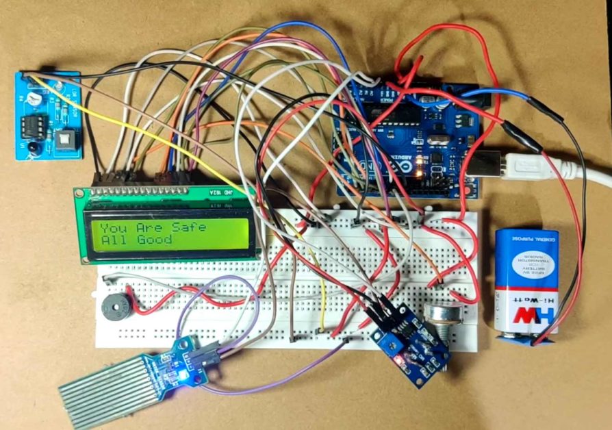
We will use a fire sensor, water sensor, gas leakage sensor, and an LCD for this project. All these sensors are connected to the Arduino. These sensors will monitor their surroundings for any fire, water, and gas-related hazard and transmit the data to the Arduino UNO board. Based on the data received by the Arduino from the sensor, the Arduino will set an alarm, and also the same thing will be displayed on the LCD. Suppose, there is a fire. The fire sensor will send data to the Arduino UNO. The Arduino will compare data with the previously stored data and set the alarm and display warning on the LCD display. It will do the same for the water and gas leakage also.
Components needed for this project
|
S. NO. |
Component Name |
Quantity |
|
1. |
Arduino UNO |
1 |
|
2. |
LPG Gas sensor |
1 |
|
3. |
Fire Sensor |
1 |
|
4. |
Water Leakage sensor |
1 |
|
5. |
16×2 LCD |
1 |
|
6. |
10K potentiometer |
1 |
|
7. |
9V battery |
1 |
|
8. |
Wires |
30 |
Circuit diagram
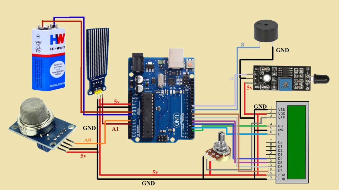
Circuit explanation
- Connect the first terminal of the potentiometer to the 5V pin of the Arduino UNO and the last terminal of the potentiometer to the GND pin of the Arduino UNO.
- Connect the GND pin of LCD to the GND pin of the Arduino UNO.
- Connect the VCC pin of LCD to the 5V pin of the Arduino UNO.
- Connect the contrast pin of the LCD to the middle pin of the potentiometer.
- Connect RS pin of the LCD to the 2nd pin of Arduino UNO.
- Connect the R/W pin of the LCD to the GND pin of the Arduino UNO.
- Connect enable pin of the LCD to 3rd pin of Arduino UNO.
- Leave the next four pins of the LCD.
- Connect d4 pin of LCD to the 4th pin of Arduino UNO.
- Connect d5 pin of the LCD to 5th pin of Arduino UNO.
- Connect the d6 of the LCD to the 6th pin of Arduino and d7 of the LCD to the 7th pin of Arduino.
- Connect the Anode pin of LCD to the 5V pin of the Arduino UNO and the cathode pin of LCD to the GND pin of the Arduino UNO.
- Connect the negative pin of the buzzer to the GND and the positive pin to the 8th pin of Arduino UNO.
- Now, connect the VCC pin of the gas sensor to the 5V.
- Connect the GND pin of the gas sensor to the GND.
- Connect the A0 pin of the gas sensor to the A0 pin of Arduino.
- Connect the VCC pin of the flame sensor to the 5V.
- Connect the GND pin of the sensor to GND.
- Connect the data pin of the sensor to the 9th pin of Arduino UNO.
- Connect the data pin of the water sensor to the A1 pin of Arduino UNO.
- Connect the positive pin of the sensor to the 5v and the negative pin of the sensor to the gnd.
- Connect the negative wire of the battery to the GND pin of Arduino UNO and connect the positive wire of the battery to the Vin pin of Arduino.
Arduino code for Home Security System
#include<LiquidCrystal.h>
LiquidCrystal mylcd(2,3,4,5,6,7);

int buzzer=8;
int fire=9;
int gas=A0;
int water=A1;


void setup() {
  // put your setup code here, to run once:
Serial.begin(9600);
mylcd.begin(16,2);
pinMode(buzzer,OUTPUT);
pinMode(fire,INPUT);
pinMode(gas,INPUT);
pinMode(water,INPUT);
}

void loop() {
  // put your main code here, to run repeatedly:
int gasData=analogRead(gas);
int waterData=analogRead(water);
int fireData=digitalRead(fire);
Serial.print("Gas Data:");
Serial.println(gasData);
Serial.print("Water Data:");
Serial.println(waterData);
Serial.print("Fire Data:");
Serial.println(fireData);

if((gasData<=700)&&(waterData<=300)&&(fireData==0))
{
  mylcd.clear();
  mylcd.setCursor(0,0);
  mylcd.print("You Are Safe");
  mylcd.setCursor(0,1);
  mylcd.print("ALL GOOD");
}

else if((gasData>700)&&(waterData>300)&&(fireData==1))
{
  tone(buzzer,500);
  delay(200);
  noTone(buzzer);
  mylcd.clear();
  mylcd.setCursor(0,0);
  mylcd.print("ALERT! ALERT!");
  mylcd.setCursor(0,1);
  mylcd.print("GAS WATER FIRE");
}

else if((gasData>700)&&(waterData>300)&&(fireData==0))
{
  tone(buzzer,1000);
  delay(200);
  noTone(buzzer);
  mylcd.clear();
  mylcd.setCursor(0,0);
  mylcd.print("ALERT! ALERT!");
  mylcd.setCursor(0,1);
  mylcd.print("GAS WATER");
}

else if((gasData<=700)&&(waterData>300)&&(fireData==1))
{
  tone(buzzer,1500);
  delay(200);
  noTone(buzzer);
  mylcd.clear();
  mylcd.setCursor(0,0);
  mylcd.print("ALERT! ALERT!");
  mylcd.setCursor(0,1);
  mylcd.print("WATER FIRE");
}

else if((gasData>700)&&(waterData<=300)&&(fireData==1))
{
  tone(buzzer,100);
  delay(200);
  noTone(buzzer);
  mylcd.clear();
  mylcd.setCursor(0,0);
  mylcd.print("ALERT! ALERT!");
  mylcd.setCursor(0,1);
  mylcd.print("GAS FIRE");
}
else if((gasData>700)&&(waterData<=300)&&(fireData==0))
{
  tone(buzzer,2000);
  delay(200);
  noTone(buzzer);
  mylcd.clear();
  mylcd.setCursor(0,0);
  mylcd.print("ALERT! ALERT!");
  mylcd.setCursor(0,1);
  mylcd.print("GAS LEAKAGE");
}

else if((gasData<=700)&&(waterData>300)&&(fireData==0))
{
  tone(buzzer,2500);
  delay(200);
  noTone(buzzer);
  mylcd.clear();
  mylcd.setCursor(0,0);
  mylcd.print("ALERT! ALERT!");
  mylcd.setCursor(0,1);
  mylcd.print("WATER LEAKAGE");
}

else if((gasData<=700)&&(waterData<=300)&&(fireData==1))
{
  tone(buzzer,3500);
  delay(200);
  noTone(buzzer);
  mylcd.clear();
  mylcd.setCursor(0,0);
  mylcd.print("ALERT! ALERT!");
  mylcd.setCursor(0,1);
  mylcd.print("FIRE! FIRE!");
}

}
Arduino Code working
Now, I will discuss the code of the Home Automation project. First, I will discuss all the possible conditions related to the sensor. These conditions will help us in deciding when to turn on and off the alarm system.
For the fire sensor we know if the sensor outputs Logic ‘1’ then there is fire. For the water sensor, if the values from the water sensor are higher than 300 then there is water leakage. And last for the gas sensor, if the values from the gas sensor are more than 700 then there is gas leakage.
We have three sensors so, there is a total of 8 possible conditions. Depending on the conditions we will set the frequency of the buzzer and display a message on the LCD.
The 1st condition is when gasdata is less than equal to 700, waterdata is less than equal to 300 and firedata is 0. That means there is no gas and water leakage and there is no fire. So, I will set the frequency to 500 Hz. And display “you are safe “and “All OK” on the LCD.
The 2nd condition is when there is gas leakage, water leakage, and fire. So, turn on the buzzer set the frequency to 500 Hz. The display message Alert Alert. Then the second message GAS Water Fire.
The 3rd condition is when there are gas leakage and water leakage and no fire. Set fire data to 0. Buzzer frequency to 10000. Set the second message to Gas water.
The 4th condition is when there are water leakage and fire. Set the frequency to 1500 / And set the second message to Water Fire.
The 5th condition is when there are gas leakage and fire. Set the second message to Gas fire.
The 6th condition is when there is only gas leakage. Change the message to gas leakage.
The 7th condition is when there is only water leakage. Set the message to water leakage. Set the frequency to 2000.
The 8th condition is when there is only fire. Then set the message to FIRE FIRE.
So, I have written all the 8 conditions.
And when nothing is there You are safe and All ok message is printed.