In this tutorial, you will learn how to design a LED chaser circuit using an Arduino UNO board. In this circuit will be turned ON/OFF LEDs one by one depending upon the pattern we want to display.
Components needed for this project
- Arduino UNO-1
- LEDs-8
- Resistor 220 ohm-8
- Jumper wires
- Breadboard
Circuit diagram of LED chaser
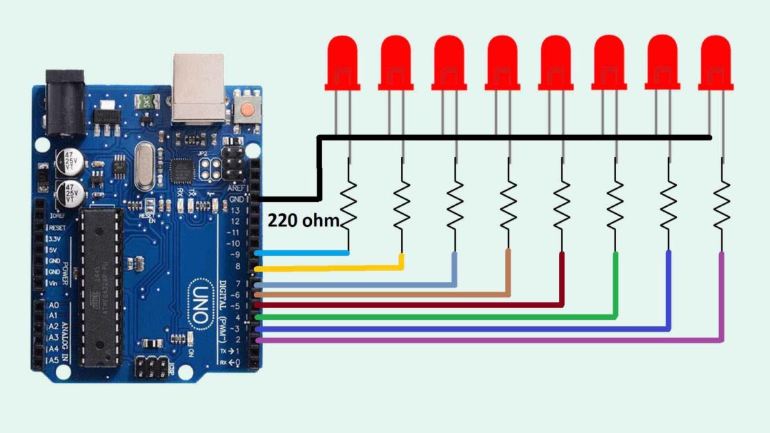
Connections
-
First, connect the GND wire of the Arduino to the power rail of the breadboard.
-
Now, insert all the LEDs onto the breadboard in such a way that you insert the negative terminal of all the LEDs in the negative power rail and the positive terminal of LEDs on the other side of the breadboard.
-
After that, insert all the resistors onto the breadboard in such a way that one terminal is connected to the positive terminal of LEDs and another terminal is connected to another side of the breadboard. Insert all the resistors one by one.
-
Now, connect the 1st LED resistor to the 2nd pin of the Arduino.
-
Connect the 2nd LED resistor to the 3rd pin of the Arduino.
-
Connect the 3rd LED resistor to the 4th pin of the Arduino.
-
Connect the 4th LED resistor to the 5th pin of the Arduino.
-
Connect the 5th LED resistor to the 6th pin of the Arduino.
-
Connect the 6th LED resistor to the 7th pin of the Arduino.
-
Connect the 7th LED resistor to the 8th pin of the Arduino
-
And in the last connect the 8th LED resistor to the 9th pin of the Arduino.
Arduino Code for LED Chaser
int led[]={2,3,4,5,6,7,8,9};
void setup() {
for(int i=0;i<8;i=i+1)
{
  pinMode(led[i],OUTPUT);
}


}
void loop() {

  for(int i=0;i<8;i=i+1)
  {
    digitalWrite(led[i],HIGH);
    delay(500);
  }

  for(int i=8;i>=0;i=i-1)
  {
    digitalWrite(led[i],LOW);
    delay(500);
  }
}
Working of Arduino code
int led[]={2,3,4,5,6,7,8,9};First, define all the pins of the Arduino UNO board where you have connected the LEDs. I have used an array for this. By using arrays it will be easy for us to perform different operations on the Arduino pins.
At pin[0], we have the first LED that is connected to pin 2 of the Arduino. Then at pin[1], we have the second LED that is connected to pin 3 of the Arduino, and so on.
void setup() {
for(int i=0;i<8;i=i+1)
{
  pinMode(led[i],OUTPUT);
}
In the void setup() function, I have set all the pins as OUTPUT using a for loop. The loop will start from 0 and goes up to 8. In an array, the indexing starts from 0. The first position in the array is 0. Then 1,2, 3, and so on. Like in array pin[]. The pin[0] is the pin 2nd pin of Arduino. Likewise, pin[1] is 3rd pin of Arduino. That is why the for loop should start from 0.
Write “for”, then inside brackets write “i=0;” 0 is the initial value of the array, then write “i<8;”, this means the loop will start from 0 and end at 7. Then write “i=i+1”. This statement will increase the value of “I” by 1.
In curly braces, write, digitalWrite, and inside bracket, write pin[i] and then OUTPUT.
When the loop will start the initial value of the “i” is 0 so, the pin[0] is set to OUTPUT. At pin[0], the 2nd pin of Arduino is stored so, the 2nd pin of Arduino is set to OUTPUT.
Then the value of “i” is increased by 1, now the value of is “i is 1. The pin stored in pin[1] is set to OUTPUT. Then again the value of “i” is increased by 1, now the value of “i” is 2. The pin stored in pin[2] is set to OUTPUT. Likewise, all the pins are set to OUTPUT.
When the value of “i” will be eight, the loop is ended because the statement “i<8” is false.
void loop() {

  for(int i=0;i<8;i=i+1)
  {
    digitalWrite(led[i],HIGH);
    delay(500);
  }
Inside the void loop() function, we have created another for loop to turn ON the LEDs one by one at an interval of 500ms.
for(int i=8;i>=0;i=i-1)
  {
    digitalWrite(led[i],LOW);
    delay(500);
  }
}
Then, we have crated another loop for turning OFF the LED one by one at an interval of 500ms.