About Obstacle Avoider Robot
In this tutorial, I will discuss the obstacle avoider robot, it’s working, and assembling.
An obstacle avoider robot is a type of autonomous robot that avoids collision with unexpected obstacles in the surroundings. It monitors its surrounding environment and looks for all the obstacles present in front of it and then it finds a path that is free of all the obstacles. These types of robots are widely used in automation industries, e-commerce, and logistics industries.
Working of Obstacle Avoider Robot
The robot is equipped with an ultrasonic distance measuring sensor that measures the distance of the nearby objects from the robot, and two DC motor with wheels for controlling the movements of the robot. When the distance of the nearby objects is greater than 20cm the robot will move in the forward direction by rotating both the motors in a forwarding direction. And when the distance of the object is 20cm or less than that the robot will turn left to avoid the obstacle. To turn left, we have to turn off the left side motor and rotate the right side motor in a forwarding direction.
Components needed for this project
|
S.No |
Component Name |
Quantity |
|
1 |
Arduino UNO |
1 |
|
2 |
Breadboard |
1 |
|
3 |
BO motor 100RPM |
2 |
|
4 |
Ball Caster Wheel |
1 |
|
5 |
9V battery and 5v Battery |
1+1 |
|
6 |
Jumper Wires |
30 |
|
7 |
L293D Motor Driver |
1 |
|
8 |
Ultrasonic sensor |
1 |
|
9 |
Chassis |
1 |
|
10 |
BO motor clamp |
2 |
|
11 |
3mm Nut bolt |
20 |
|
12 |
Spacers |
2 |
Circuit diagram of the Obstacle Avoider Robot
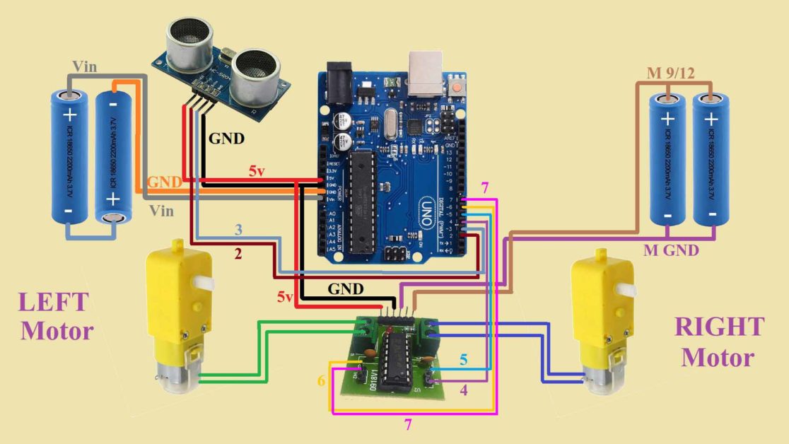
Now, I will discuss the circuit diagram of the obstacle avoider robot.
First, we have our main component that is an Arduino UNO board that will control all the sensors and motor. Then a distance measuring sensor to measure the distance of the nearby objects. Its VCC and GND pins are connected to the 5V and GND pin of the Arduino UNO board respectively. The trigger pin of the sensor is connected to the 2nd pin of the Arduino UNO board and the echo pin of the sensor is connected to the 3rd pin of the Arduino UNO board.
You can see in the circuit diagram, I have used different color wires for each connection and assign a pin number to the wire where they are connected. For example, the red wire is connected to the 5V pin of the Arduino UNO board so, I have mentioned 5V near the red wire. This is the same for the other wires.
Let us move to the other part of the circuit. We have two motors, one for the left wheel and the other for the right wheel. Both these motors are connected to the terminals on the motor driver. You don’t have to worry about the polarity of the motor, you can switch the input signal wire to switch between the polarity.
For controlling the motion of the right motor we have two pins that are connected to the D4 and D5 pins of the Arduino UNO Board. Similarly, we have two pins to control the motion of the left motor which are connected to the D6 and D7 pins of the Arduino UNO board.

Now, these 6 pins are left. Starting two pins are for connecting 5 volts. You can use any of the pins as they both are connected internally. Then the next two pins are for the GND pins. These two pins are also connected internally. On one pin, you have to connect the GND pin of the Arduino UNO board and on the other pin, you have to connect the negative terminal of the External battery. The last two pins are also connected internally. These two pins are for connecting the positive terminal of the external battery.
I am using two separate batteries. The first one is for powering the Arduino board and the second one is for powering the motors. I have used two Li-ion cells in both batteries. In the first battery, I have connected them in series to get the output voltage of 8volts. These individuals when are fully charged output 4 volts. So I have connected two in series. I will get 8 volts from them. You can use any other battery whose voltage is above 7.5 volts.
In the next battery, I have connected the cell in a parallel configuration to get the voltage of 4 volts. These motors work on 3-6 volts. You can also replace this battery with a battery whose voltage is between 3.7- 6 volts and the current capacity is 2 amps.
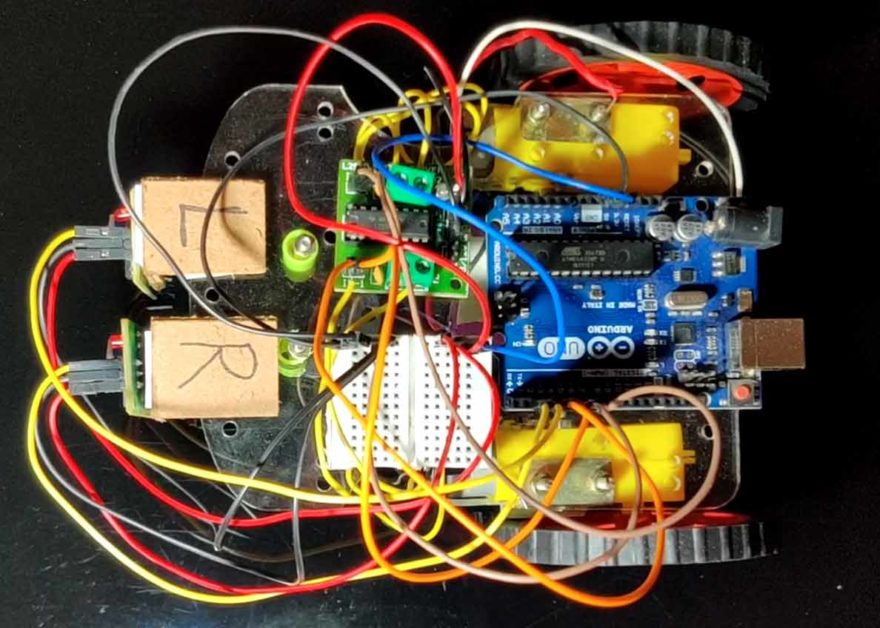
Assemble the robot as shown in the picture
Arduino code for Obstacle Avoider Robot
//Define pins for the ultrasonic sensor and motor
int trigPin=2;
int echoPin=3;
int rightMotor1=4;
int rightMotor2=5;
int leftMotor1=6;
int leftMotor2=7;
// Create two variable for storing time from the sensor and distance of the object
long d;
int dist;

void setup() {
  // Set baud rate for the serial communication
Serial.begin(9600);

// Set all the pins INPUT/OUTPUT depending upon their function
pinMode(trigPin,OUTPUT);
pinMode(echoPin,INPUT);
pinMode(rightMotor1,OUTPUT);
pinMode(rightMotor2,OUTPUT);
pinMode(leftMotor1,OUTPUT);
pinMode(leftMotor2,OUTPUT);
}

void loop() {
  //Write code for measuring distance of the object
digitalWrite(trigPin,LOW);
delayMicroseconds(2);
digitalWrite(trigPin,HIGH);
delayMicroseconds(10);
digitalWrite(trigPin,LOW);
d=pulseIn(echoPin,HIGH);
dist=d*0.034/2;
Serial.println(dist);

if(dist<=20)
{
  digitalWrite(rightMotor1,HIGH);
  digitalWrite(rightMotor2,HIGH);
  digitalWrite(leftMotor1,HIGH);
  digitalWrite(leftMotor2,LOW);
  delay(200);
}
else
{
  digitalWrite(rightMotor1,LOW);
  digitalWrite(rightMotor2,HIGH);
  digitalWrite(leftMotor1,HIGH);
  digitalWrite(leftMotor2,LOW);
}
}