What is RFID and how does it work?
The RFID(Radio Frequency Identification) is a type of technology that is based on radio frequencies and used for the identification of different devices or objects. The RFID has two main components one is an RFID tag and the other one is an RFID reader. Each RFID tag has a unique identification number that can only be read by the RFID reader. The RFID reader consists of a radiofrequency generator and an antenna that emits strong electromagnetic waves for reading data from the RFID tag. The RFID tag is passive in nature that means it does not have its own power source. It also consists of a small antenna.
When the RFID reader emits strong electromagnetic waves, these waves hit the RFID tag due to which a voltage is induced in the RFID Tag and it emits back electromagnetic waves using that small antenna that is present inside the RFID tag. That electromagnetic wave consists of an identification number associated with that RFID tag. Then, the RFID readers capture those electromagnetic waves from the RFID tag and read the identification number. It is similar to bar code reading. Now, a days RFID is used almost everywhere like in toll tax collections, malls, security systems, and many more. There are a variety of RFID writers and Readers available. In the tutorial, we will learn about the RC522 RFID 13.56MHZ Reader Writer Module
About RC522 RFID 13.56MHZ Reader Writer Module
This RFID reader uses a 13.56MHZ electromagnetic wave for reading information from the RFID tag. In order to see the RFID tag identification number, you can easily interface this RFID reader with any microcontroller using a four-wire communication that is SPI communication. You can get a maximum data rate of 10Mbps using this type of communication. This module can also communicate with the microcontroller using I2C and UART communication protocol. You can power this module with a voltage between 2.5 to 3.3V.
Pin configuration of RC522 RFID 13.56MHZ Reader Writer Module
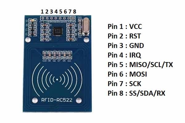
RC522 RFID module Pin uses
- The VCC pin is used to connect 3.3V to the module.
- The GND pin is used to connect GND to the module.
- The RST pin is used for resetting the board.
- If you are using the UART communication protocol for interfacing the module with the Arduino UNO then you have to use pin 5 and pin 8. Pin 5 is TX pin and Pin 8 is RX pin.
- If you are using the I2C communication protocol for interfacing the module with the Arduino UNO then you have to use pin 5 and pin 8. Pin 5 is the SCL pin and pin 8 is the SDA pin.
- If you are using SPI communication protocol for interfacing the module with the Arduino UNO then you have to use pin 5, pin 6, pin 7 and pin 8. Pin 5 is the MISO pin, pin 6 is the MOSI pin, pin 7 is the SCK pin and pin 8 is the SS pin.
- The IRQ pin is an interrupt pin. Used to wake up the module when a device comes into range.
Features of RC522 RFID 13.56MHZ Reader Writer Module
- Operating Voltage: 2.5-3.3V
- Operating Current: 13-26mA
- Operating temperature: -20°C to 80°C
- The frequency used: 13.56MHZ
- Range: 5cm
- Maximum data rate: 10Mbps
- Power down mode: 10uA
- Communication Protocols: SPI, I2C and UART
Components needed for this tutorial
- RC522 RFID 13.56MHZ Reader Writer Module
- RFID tag
- Breadboard
- Arduino UNO
- Jumper wires
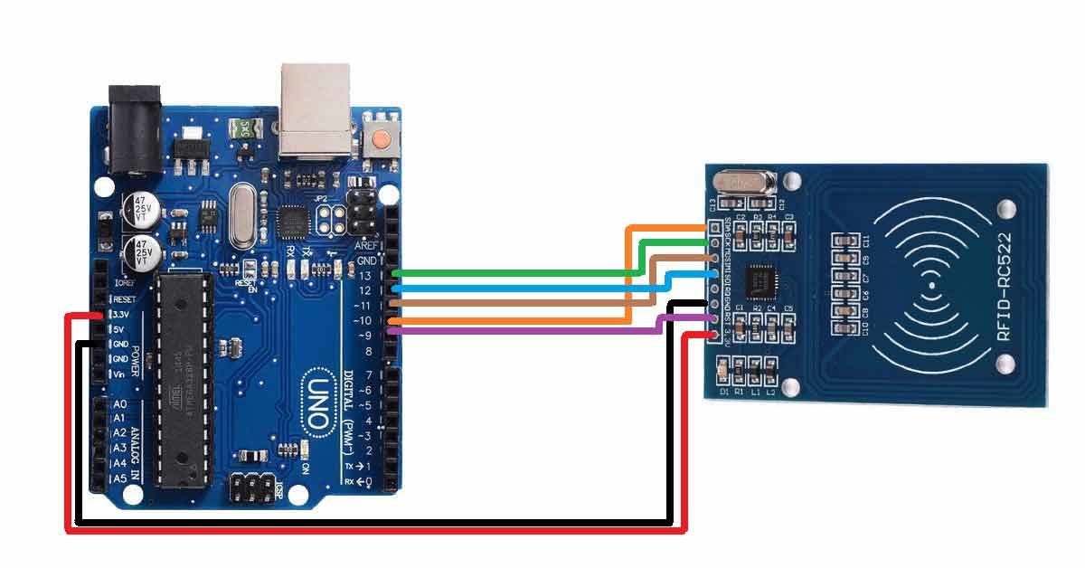
RC522 RFID reader connections with Arduino UNO
- Connect the VCC pin of the module to the 3.3V pin of Arduino UNO.
- Connect the GND pin of the module to the GND pin of the Arduino UNO.
- Connect the RST pin of the module to the D9 pin of the Arduino UNO.
- Connect the MOSI pin of the module to the D11 pin of the Arduino UNO.
- Connect the MISO pin of the module to the D12 pin of the Arduino UNO.
- Connect the SCK pin of the module to the D13 pin of the Arduino UNO.
- Connect the SS pin of the module to the D10 pin of the Arduino UNO.
Circuit diagram of RC522 RFID module with Arduino
Before uploading code to the Arduino UNO board, download the RFID library from this link: https://github.com/song940/RFID-RC522
Arduino code for RC522 RFID Module
//Include all the necessary libraries in your code. We only need two libraries, one for SPI and communication and one for RFID reader.
#include <SPI.h>
#include <RFID.h>

//Define two pins, one for SS pin and other for RST pin of the module.
#define SS_PIN 10
#define RST_PIN 9

//Create and object named rfid of type RFID and pass SS pin and RST pin inside it. Create one array also for storing the data coming from the RFID tag.
RFID rfid(SS_PIN,RST_PIN);
int serNum[5];
void setup(){

//In the void setup() function, initiate serial communication, SPI communication and RFID.
    Serial.begin(9600);
    SPI.begin();
    rfid.init();

}

//Print the data of the RFID tag on the serial monitor.
void loop(){
    if(rfid.isCard()){
        if(rfid.readCardSerial()){
            Serial.print(rfid.serNum[0]);
            Serial.print(" ");
            Serial.print(rfid.serNum[1]);
            Serial.print(" ");
            Serial.print(rfid.serNum[2]);
            Serial.print(" ");
            Serial.print(rfid.serNum[3]);
            Serial.print(" ");
            Serial.print(rfid.serNum[4]);
            Serial.println("");
        }
    }
    rfid.halt();
}