About this project and it’s working
In this tutorial, I will discuss how to make a smart door lock system using an Arduino UNO, a keypad, and a solenoid door lock.
We will use the keypad to lock and unlock this lock. The password for this lock will be stored in the Arduino code that you can change whenever you want.
Suppose the password of the lock is 333. When the user presses any key on the keypad the Arduino will first check whether the key is pressed or not. If the key is pressed and the pressed key is 3 and pressed three times in a row. The password is correct, the Arduino will open the lock. If the password is wrong the lock will remain closed.
Components needed for this project
|
S. No. |
Component Name |
Quantity |
|
1. |
Arduino UNO |
1 |
|
2. |
4×3 Keypad matrix |
1 |
|
3. |
Solenoid door lock |
1 |
|
4. |
9V battery |
1 |
|
5. |
5V relay module |
1 |
|
6. |
LEDs Red and blue |
2 |
|
7. |
Resistor 220 ohm |
2 |
|
8. |
Wires |
20 |
Circuit diagram of Smart Door Lock System
Circuit explanation
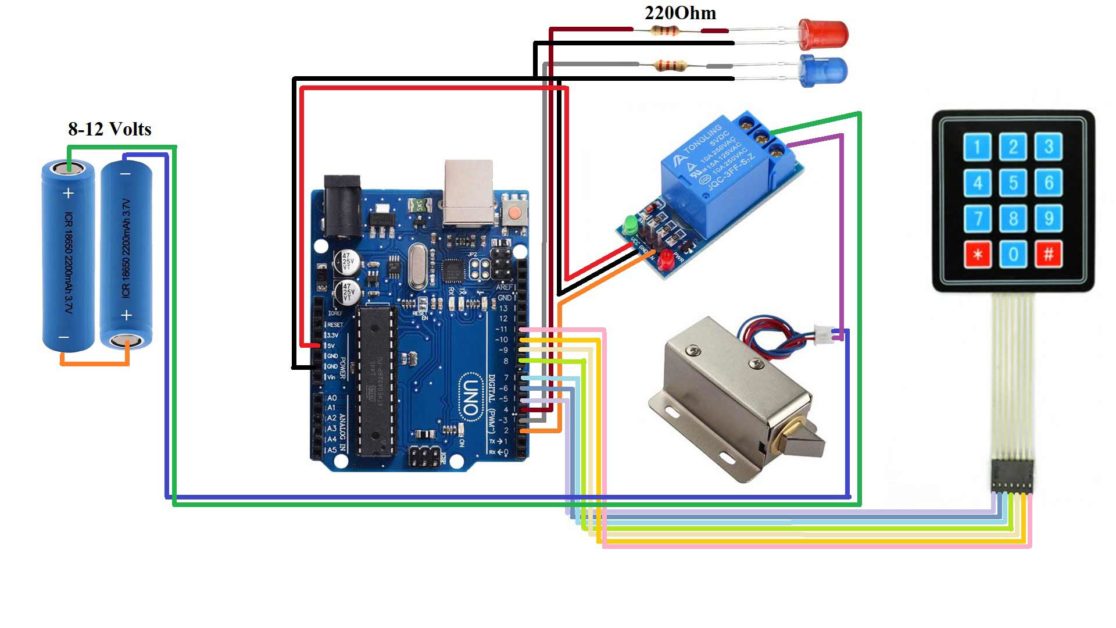
This is the circuit diagram that I gonna use for this project. I have one Arduino UNO board and a keypad is connected to it. Its row pins are connected to the 5th,6th,7th, and 8th pin of Arduino UNO. Its column pins are connected to the 9th, 10th, and 11th pin of the Arduino UNO.
The negative terminal of both the LEDs is connected to the GND of Arduino UNO. The positive terminal of the Blue LED is connected to a 220ohm resistor and then that resistor is connected to the 3rd pin of Arduino UNO. Similarly, the positive terminal of Red LED is connected to a 220-ohm resistor and then the resistor is connected to the 4th pin of the Arduino UNO.
The VCC pin of the relay module is connected to the 5V pin or Arduino UNO. The GND pin of the relay is connected to the GND pin of the Arduino UNO, and the input pin of the relay module is connected to the 2nd pin of the Arduino UNO.
The negative terminal of the battery is connected to the negative wire of the solenoid door lock. The positive terminal of the battery is connected to the COM pin of the relay module and the positive wire of the solenoid door lock is connected to the NO pin of the relay module.
Before uploading code to the Arduino UNO, download and install this library in Arduino IDE from this link: https://github.com/Chris–A/Keypad
Arduino code for Smart Door Lock System
#include<Keypad.h>
int lock=2;
int ledBlue=3;
int ledRed=4;
int count=0;
const byte numRows=4;
const byte numCols=3;
char keymap[numRows][numCols]={
{'1','2','3'},
{'4','5','6'},
{'7','8','9'},
{'*','0','#'},
};
byte rowPins[numRows]={5,6,7,8};
byte colPins[numCols]={9,10,11};
Keypad myKeypad=Keypad(makeKeymap(keymap),rowPins,colPins,numRows,numCols);


void setup() {

Serial.begin(9600);
pinMode(lock,OUTPUT);
pinMode(ledRed,OUTPUT);
pinMode(ledBlue,OUTPUT);
digitalWrite(lock,HIGH);
}

void loop() {

char keypressed=myKeypad.getKey();
if(keypressed!=NO_KEY)
{
  Serial.println(keypressed);
  if(keypressed=='3')
  {
    count=count+1;
  }
  if(count>3)
  {
    count=0;
  }
  if((keypressed=='*')&&(count==4))
  {
    digitalWrite(lock,LOW);
    digitalWrite(ledBlue,HIGH);
    digitalWrite(ledRed,LOW);
    count=0;
  }
  if(keypressed=='#')
  {
    digitalWrite(lock,HIGH);
    digitalWrite(ledRed,HIGH);
    digitalWrite(ledBlue,LOW);
    count=0;
  }
}
}
Arduino Code working
#include<Keypad.h>Include the library for the keypad. This library will contain all the basic coding for interfacing a keypad and some functions that we will use directly in the our main code.
int lock=2;
int ledBlue=3;
int ledRed=4;
int count=0;
Define one variable for relay input pin that is lock. Define one pin for blue LED and one pin for red LED.
Create one count variable and store value 0 in it. We will use this variable to count the number of times a particular key is pressed.
const byte numRows=4;
const byte numCols=3;
Create two more variable and assign total number of rows and column to them.
char keymap[numRows][numCols]={
{'1','2','3'},
{'4','5','6'},
{'7','8','9'},
{'*','0','#'},
};
Create one two dimensional array and store the key that are present on the keypad.
byte rowPins[numRows]={5,6,7,8};
byte colPins[numCols]={9,10,11};
Define the column and row pin of the keypad.
Keypad myKeypad=Keypad(makeKeymap(keymap),rowPins,colPins,numRows,numCols);Create a keypad by passing all the parameters that we have mentioned above.
void setup() {
  // put your setup code here, to run once:
Serial.begin(9600);
pinMode(lock,OUTPUT);
pinMode(ledRed,OUTPUT);
pinMode(ledBlue,OUTPUT);
digitalWrite(lock,HIGH);
}
In the void setup() function, set the baud rate for serial communication, set lock pin and LED pins as OUTPUT. Set lock pin as HIGH to turn OFF the LOCK.
void loop() {

char keypressed=myKeypad.getKey();
if(keypressed!=NO_KEY)
{
  Serial.println(keypressed);
  if(keypressed=='3')
  {
    count=count+1;
  }
  if(count>3)
  {
    count=0;
  }
In the void loop() function, write the code for reading the key of the keypad. If the key pressed is 3 then we will increase the count by one. And if the count value reaches above 3 then we will reset it to 0 again.
if((keypressed=='*')&&(count==3))
  {
    digitalWrite(lock,LOW);
    digitalWrite(ledBlue,HIGH);
    digitalWrite(ledRed,LOW);
    count=0;
  }
After pressing the correct code, the user has to press ‘*’. If ‘*’ is pressed and the count value is equal to 3, the lock will be opened and blue LED will is also turned ON and the red led is turned OFF.
if(keypressed=='#')
  {
    digitalWrite(lock,HIGH);
    digitalWrite(ledRed,HIGH);
    digitalWrite(ledBlue,LOW);
    count=0;
  }
}
}
IF the password is incorrect or ‘#’ is pressed the lock will be closed and blue LED will be turned OFF and red LED will be turned ON.