20X4 LCD: An Overview
A 20×4 LCD, also known as a Liquid Crystal Display, is a widely used device for displaying text and data. This type of display has 20 columns and 4 rows of characters, allowing for 80 characters to be displayed at once. The 20×4 LCD is commonly used in a variety of applications, such as in electronic devices, home appliances, and industrial systems.
The LCD consists of a matrix of liquid crystal cells that can be controlled to block or transmit light, thus forming characters and symbols. The LCD operates by applying a voltage to the liquid crystal cells, which causes the light to be either blocked or transmitted. The LCD is typically paired with a backlight, which provides illumination for the display.
The 20×4 LCD is controlled by an interface, typically a microcontroller or a microprocessor, which sends commands and data to the display. The interface is responsible for sending the voltage signals to the liquid crystal cells, which cause the characters to be displayed. The interface also controls the contrast of the display and the brightness of the backlight.
When it comes to interfacing a 20×4 LCD with a microcontroller or microprocessor, there are several options available. One common method is to use an integrated circuit (IC) that interfaces with the LCD. This type of IC, known as a Character LCD Controller, handles the voltage signals and communication between the microcontroller and the LCD. Another option is to use a library that is specific to the microcontroller, which handles the low-level communication with the LCD.
In this article, we will go over the steps to connect and interface a 20×4 LCD with an Arduino board.
Pin Diagram of 20X4 LCD
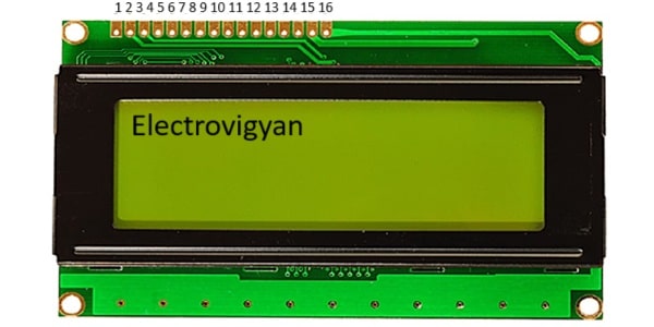
A 20×4 LCD has 20 columns and 4 rows of characters and typically has 16 or 20 pins, depending on the type of interface it uses. Here is a common pin diagram for a 20×4 LCD:
- Ground (GND) – Connected to ground
- Vcc – Connected to the power supply voltage, usually +5V
- Vo – Adjusts the contrast of the display by controlling the backlight brightness
- RS (Register Select) – Selects between data and command mode
- R/W (Read/Write) – Selects between read and write mode
- E (Enable) – Used to enable writing to the LCD
- D0 to D7 – Data pins used to send data to the LCD
- A and K – Connected to the positive power supply for the backlight
- LED+ and LED- – Connected to the positive and negative power supply for the backlight, respectively.
Specification of 20X4 LCD
-
Display Type: The 20×4 LCD is a type of alphanumeric display that can show characters and symbols. It has 20 columns and 4 rows of characters.
-
Character Size: The character size is usually defined in terms of the number of dots (pixels) used to form a character. The typical character size for a 20×4 LCD is 5×8 dots or 5×11 dots.
-
Resolution: The resolution of a 20×4 LCD is the number of columns and rows of characters that it can display. The resolution of a 20×4 LCD is 20 columns x 4 rows = 80 characters.
-
Interface: The interface used to connect the 20×4 LCD to the microcontroller or control board can vary. Some common interfaces include 8-bit parallel, 4-bit parallel, and serial.
-
Operating Voltage: 5V
-
Operating Temperature: 0°C to 50°C.
-
Storage Temperature: -20°C to 70°C.
These are some of the common specifications of a 20×4 LCD. It’s important to check the datasheet for the specific model for the exact specifications.
Interfacing 20X4 LCD with Arduino Board
Materials Needed:
- Arduino board (Uno, Mega, etc.)
- 20×4 LCD display
- Breadboard
- Jumper wires
- Potentiometer (10K)
- 220Ω resistor
Circuit Diagram of Interfacing 20X4 LCD with Arduino Board
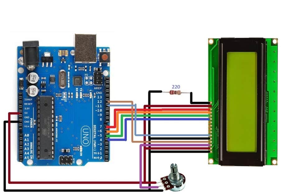
Take the 16×4 LCD and place it onto the breadboard.
Connect the LCD’s VCC pin to the 5V pin on the Arduino
Connect the GND pin to one of the GND pins on the Arduino
Connect the RS (register select) pin to digital pin 12 on the Arduino
Connect the RW (read/write) pin to GND on the Arduino
Connect the E (enable) pin to digital pin 11 on the Arduino
Connect the D4 pin to digital pin 4 on the Arduino
Connect the D5 pin to digital pin 5 on the Arduino
Connect the D6 pin to digital pin 6 on the Arduino
Connect the D7 pin to digital pin 7 on the Arduino
Connect the contrast pin (Vo) to the middle terminal of the potentiometer
Connect one terminal of the Potentiometer to the GND and the remaining terminal to the 5V.
Step 4: Upload the Code To upload the code, open the Arduino IDE and select the right board and port. Then copy and paste the following code:
Arduino Code for Interfacing 20X4 LCD with Arduino Board
#include <LiquidCrystal.h> // Include the LiquidCrystal library

LiquidCrystal lcd(12, 11, 4, 5, 6, 7); // Define the LCD pins

void setup() {
  lcd.begin(20, 4); // Initialize the LCD with 20 columns and 4 rows
  lcd.clear(); // Clear the display
}

void loop() {
  lcd.setCursor(0, 0); // Set the cursor position to the first row and first column
  lcd.print("I Love Electronics"); // Print "Line 1" to the first row

  lcd.setCursor(0, 1); // Set the cursor position to the second row and first column
  lcd.print("I Love Arduino"); // Print "Line 2" to the second row

  delay(1000); // Wait for 1 second
}
Arduino Code Explanation
In this code, the LiquidCrystal library is included to provide the necessary functions for controlling the LCD. The LCD is connected to digital pins 12, 11, 4, 5, 6, and 7, and these pins are defined in the LiquidCrystal object.
In the setup() function, the begin() method is used to initialize the LCD with 20 columns and 4 rows. The clear() method is used to clear the display.
In the loop() function, the setCursor() method is used to set the cursor position to the first row and first column, and then the print() method is used to print “Line 1” to the first row. The cursor position is then set to the second row and first column, and “Line 2” is printed to the second row. The delay() function is used to wait for 1 second.
This code is just a basic example to demonstrate how to display two lines of text on a 20×4 LCD. You can modify the code to display different texts or perform other operations with the LCD.