What is a sensor?
A sensor is a device, module, machine, or subsystem that detects the changes in its environment, produces an output signal and sends the information to other electronics (e.g. a computer processor) for the purpose of sensing a physical phenomenon.
Eg. Flame sensors, analog sensors, ultrasonic sensors etc.
What is an IR sensor?
An infrared (IR) sensor is an electronic device that measures and detects infrared radiation (wavelength in the range of 760 nm to 1100 nm) in its surrounding environment. E.g. Heat emitted at a temperature above around five degrees Kelvin gives off infrared radiation.
What is a Flame sensor?
A flame sensor is a type of sensor that is used to detect flames. It consists of an IR diode that receives IR rays emitted by the flames, then based on the intensity of the IR rays detected by the IR diode, it will output a signal. That output signal is then sent to the comparator that is present on the module. The comparator then compares the signal value with the value that is set by us using a potentiometer present on the module. If the signal value matches the value of the potentiometer then you will get Logic 1 on the D0 pin of the sensor otherwise you will get Logic 0 on the D0 pin. And on the A0 pin of the sensor, you will get the analog values directly from the IR diode.
An IR flame sensor has a wide array of applications such as hydrogen stations, gas-fueled cookers, industrial heating and drying systems, domestic heating systems, fire fighting robots etc.
The applicability of an IR sensor is enhanced by the following features:
High photosensitivity
Fast response
Simple to use
Adjustable accuracy and sensitivity
Pin configuration of the Flame sensor
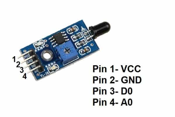
Pin uses
- Pin 1 is the VCC pin used to connect the 5v to the module.
- Pin 2 is the GND pin used to connect the ground to the module.
- Pin 3 is the D0 pin used to get the digital data logic 1 and 0 from the sensor.
- Pin 4 is the A0 pin used to get the analog data in the range of 0-5v from the sensor.
Features of the flame sensor
- The operating voltage of the sensor is between 3.5-5V DC.
- The operating current of the sensor is <15mA.
- It outputs digital data 0 or 1.
- It outputs analog data from 0 to 5 volts.
- Two LEDs are also present on the module, one for the indication of power status and another for the indication of flame detection.
- The LM393 operational amplifier is used inside the module.
Components used
- Arduino UNO
- One Flame sensor
- Breadboard
- Jumper wires
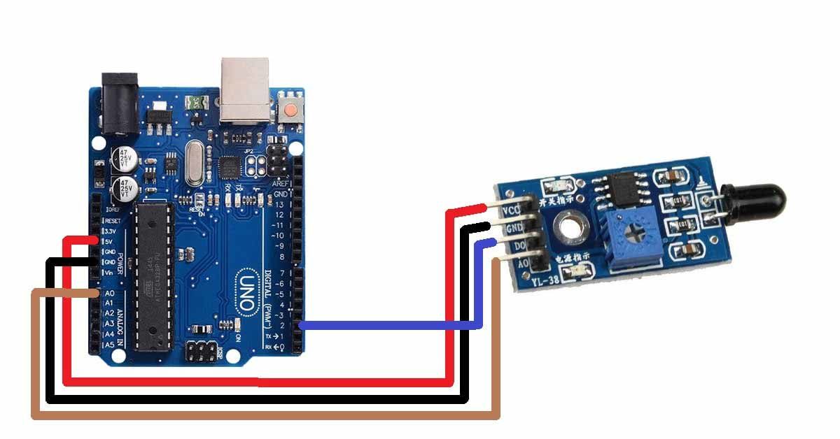
Pin connections of the flame sensor with Arduino
- Connect the VCC pin of the sensor to the 5v pin of the Arduino UNO.
- Connect the GND pin of the sensor to the GND pin of the Arduino UNO.
- Connect the D0 pin of the sensor to the D2 pin of the Arduino UNO.
- Connect the A0 pin of the sensor to the A0 pin of the Arduino UNO.
Circuit diagram of the Flame sensor with Arduino UNO
Arduino code for the Flame sensor
const int sensorA=A0;/Define pin for analog pin of the sensor
const int sensorD=D2;//Define pin for digital pin of the sensor
void setup() {

Serial.begin(9600);//Set baud rate for the serial communication
pinMode(sensorA,INPUT);//Set analog pin as INPUT
pinMode(sensorD,INPUT);//Set digital pin as INPUT
}

void loop() {
  int sensorAnalog = analogRead(sensorA);//for analog data
  int sensorDigital = digitalRead(sensorD);//for digital data
  Serial.print("AnalogData:");
  Serial.println(sensorAnalog);//Print analog values on the serial monitor
  Serial.print("DigitalData:");
  Serial.println(sensorDigital);//Print digital values on the serial monitor
  delay(500);
}