What is an L293D motor driver?
The L293D motor driver is used to drive two motors simultaneously. Further, the direction of each motor can be controlled independently. This IC works on the principle of the quadruple high-current half-H bridge. H-bridge is a setup that is used to run the motor in both clockwise and anticlockwise directions. You can easily drive a motor of up to 36 volts and whose maximum current consumption is 600mA using this IC. Also, it is used to control other inductive loads such as relays and bipolar stepping motors. This driver is used to design DC motor drivers, stepper motor drivers, and latching relay drivers.
Pin configuration the of L293D motor driver
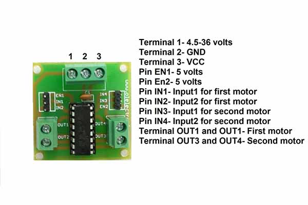
Pin uses
- Terminal 1 is used to connect the positive terminal of the power supply for the motor. The voltage must be between 4.5 to 36 volts.
- terminal 2 is used to connect the GND of the Arduino and the negative terminal of the power supply used for the motor.
- Terminal 3 is used to connect 5 volts for logic.
- Pin EN1 is used to enable the first motor.
- Pin IN1 is used to rotate the first motor in the clockwise direction.
- Pin IN2 is used to rotate the first motor in the anti-clockwise direction.
- Pin EN2 is used to enable the second motor.
- Pin IN3 is used to rotate the second motor in the clockwise direction.
- Pin IN4 is used to rotate the second motor in the anti-clockwise direction.
- Terminal OUT1 and OUT2 are used to connect the first motor.
- Terminal OUT3 and OUT4 are used to connect the second motor.
Features of L293D motor driver
- The operating voltage is between 4.5-36 volts.
- The maximum current output for each motor is 600mA.
- The operating temperature is between 0°C-70°C.
- The peak output current is 1.2A.
- Internal Electrostatic discharge protection.
- Sperate input-logic supply.
Components needed
- Arduino UNO
- L293D motor driver
- Breadboard
- Two DC motors
- Breadboard
- Jumper wires
- One 9-volt battery
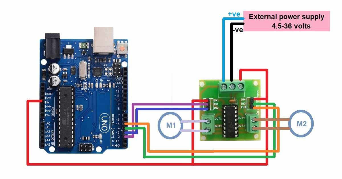
Pin connections of L293D with Arduino UNO
- Connect the first motor’s positive terminal to OUT1.
- Connect the first motor’s negative terminal to OUT2.
- Connect the second motor’s positive terminal to OUT3.
- Connect the second motor’s negative terminal to OUT4.
- Connect the EN1 and EN2 pins to the 5 volts.
- Connect the IN1 pin to the D2 pin of the Arduino UNO.
- Connect the IN2 pin to the D3 pin of the Arduino UNO.
- Connect the IN3 pin to the D4 pin of the Arduino UNO.
- Connect the IN4 pin to the D5 pin of the Arduino UNO.
- Connect the positive terminal of the external power supply to terminal 1 of the motor driver.
- Connect the negative terminal of the external power supply and GND pin of Arduino to terminal 2 of the motor driver.
- Connect terminal 3 of the motor driver to the 5-volt pin of the Arduino.
Circuit diagram of L293D motor driver with Arduino UNO
Arduino code for L293D motor driver
//Define all the input pins of the motor driver
const int motor1input1=2;
const int motor1input2=3;
const int motor2input1=4;
const int motor2input2=5;

void setup() {

Serial.begin(9600);
//Set baud rate for serial communication
//Set all the pin as OUTPUT
pinMode(motor1input1,OUTPUT);
pinMode(motor1input2,OUTPUT);
pinMode(motor2input1,OUTPUT);
pinMode(motor2input2,OUTPUT);
//Set all the pin to Logic HIGH to initially turn off the motor
  digitalWrite(motor1input1,HIGH);
  digitalWrite(motor1input2,HIGH);
  digitalWrite(motor2input1,HIGH);
  digitalWrite(motor2input2,HIGH);
}

void loop() {
  digitalWrite(motor1input1,LOW);
//Turn first motor in clockwise direction
  //digitalWrite(motor1input2,LOW);

//uncomment this to rotate first motor in anti-clockwise direction
  digitalWrite(motor2input1,LOW);

//Turn second motor in anti-clockwise direction
  //digitalWrite(motor2input2,LOW);

//uncomment this to rotate second motor in anti-clockwise direction
}