PIR Sensor Module: An overview
A PIR sensor is a type of sensor that detects motion by sensing changes in infrared radiation (heat) in its field of view. The acronym PIR stands for “Passive Infrared.” PIR sensors are commonly used in security systems, such as burglar alarms and motion-activated lights, and in automation systems, such as smart home devices. They are also used in heating, ventilation, and air conditioning (HVAC) control systems and other applications where motion detection is required.
The sensor consists of a pyroelectric material, typically crystalline in nature, that generates an electrical charge in response to changes in temperature. When an object or person moves within the sensor’s field of view, the heat emitted by the object changes, causing a corresponding change in the electrical charge generated by the pyroelectric material. This change in charge is then processed by the sensor’s electronics to produce an output signal indicating the presence of motion.
PIR sensors are passive devices, meaning they do not emit any energy or light, making them ideal for use in environments where light emission is not desired. They are relatively cheap and easy to install, making them accessible for a wide range of applications.
The sensor is designed so that its field of view is focused in one direction. When an object moves within the field of view, the heat generated by the object is sensed by the pyroelectric material, producing a change in electrical charge. The sensor’s electronics detect this change and process it to produce an output signal, indicating the presence of motion.
PIR sensors are designed to have a certain time delay, known as the hold-time after motion is detected. This allows the sensor to remain active for a set amount of time after a motion has been detected, to ensure that any subsequent movement is also detected.
Pin Diagram of PIR sensor Module
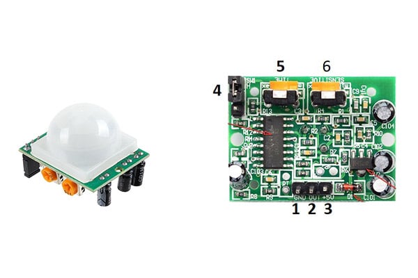
A typical PIR sensor module consists of the following pins:
-
GND: The ground pin.
- OUT: The output pin, which provides a high or low signal depending on whether motion has been detected.
- VCC: The positive power supply pin, typically 5V.
-
TRIG: An optional trigger pin, used to manually trigger the sensor.
-
ADJ Time: An optional adjustment pin, used to adjust the alarm time.
-
ADJ Sensitivity: An optional adjustment pin, used to adjust the sensitivity of the sensor.
Specifications of a PIR Sensor Module
-
Power Supply: The operating voltage required by the module, typically between 3V and 12V.
-
Detection Range: The maximum distance the sensor can detect motion, typically between 5 and 20 meters.
-
Field of View: The angle of detection, usually specified in degrees, ranging from 60 to 180 degrees.
-
Sensitivity: The ability of the sensor to detect small movements, usually adjustable through an onboard potentiometer or a separate sensitivity pin.
-
Time Delay: The time delay between the detection of motion and the output signal, typically adjustable through an onboard potentiometer or a separate time delay pin.
-
Output Type: The type of output signal produced by the module, typically a digital signal, such as a high or low voltage, or an analog signal.
-
Operating Temperature: The range of temperatures over which the sensor can operate, typically specified in degrees Celsius.
-
Dimensions: The physical size of the module, typically specified in millimetres.
-
Connectivity: The type of interface used for communication with other devices, such as a digital output, an I2C interface, or a serial interface.
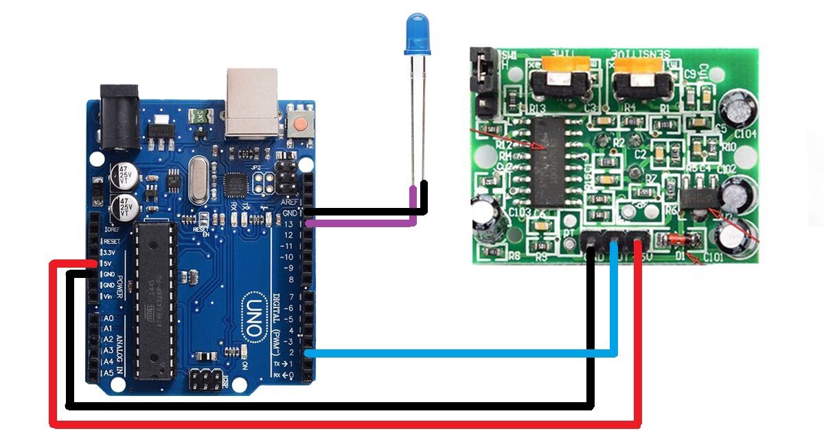
Circuit Diagram For Interfacing PIR Sensor Module With Arduino Board
Materials required:
- PIR Sensor
- Arduino board (UNO, Mega, etc.)
- Breadboard
- Jumper Wires
- LED
- 220Ω Resistor
Steps to interface PIR Sensor with Arduino
-
Connect the PIR Sensor: Connect the VCC pin of the PIR sensor to the 5V pin of the Arduino board, the GND pin to the GND pin of the Arduino board, and the OUT pin to the digital pin 2 on the Arduino board.
-
Connect the LED: Connect the anode (positive) of the LED to the digital pin 13 of the Arduino board and the cathode (negative) to the GND pin of the board through a 220Ω resistor.
-
Upload the code: The code for this project is very simple and only requires a few lines of code. The following code will turn on the LED when the PIR sensor detects motion.
const int ledPin = 13;   // the pin that the LED is attached to
const int pirPin = 2;    // the pin that the PIR sensor is attached to

void setup() {
  pinMode(ledPin, OUTPUT);
  pinMode(pirPin, INPUT);
}

void loop() {
  if (digitalRead(pirPin) == HIGH) {
    digitalWrite(ledPin, HIGH);   // turn the LED on
  } else {
    digitalWrite(ledPin, LOW);    // turn the LED off
  }
}- Test the circuit: After uploading the code, the circuit is now ready to be tested. If everything is set up correctly, the LED should turn on when the PIR sensor detects motion.
The alarm time and detection range of a PIR sensor can be adjusted to suit the specific needs of your project. Here’s how to adjust these settings:
-
Alarm Time: The alarm time is the amount of time that the PIR sensor will remain in an alarm state after detecting motion. This time can usually be adjusted by adjusting the duration of the output signal from the sensor. To do this, locate the “time” or “duration” adjuster on the PIR sensor and adjust it to your desired alarm time. The adjuster may be in the form of a potentiometer or a switch that changes the duration of the output signal.
-
Detection Range: The detection range of a PIR sensor is the maximum distance at which the sensor can detect motion. To adjust the detection range, locate the “sensitivity” adjuster on the sensor and adjust it until you get the desired range. Like the alarm time adjuster, the sensitivity adjuster may be in the form of a potentiometer or a switch.
It’s important to note that the exact location and type of adjusters may vary depending on the specific PIR sensor model. So, it’s always best to consult the manufacturer’s documentation for more information on how to adjust the alarm time and detection range of your PIR sensor.
In conclusion, adjusting the alarm time and detection range of a PIR sensor is a simple process that can help you optimize its performance for your specific application. By following these steps, you can fine-tune the sensor to detect motion in the desired range and for the desired duration, ensuring that your project functions as desired.