7-segment displays are a type of digital display that is commonly used to display numerical information. They consist of seven individual segments that can be lit up to form the numbers 0-9. This simple and cost-effective technology is widely used in a variety of applications, from electronic calculators and digital clocks to digital signage and industrial control systems.
Advantages of 7 Segment Displays
7 segment displays offer several advantages, including:
-
Simplicity: 7-segment displays are simple to understand and use, making them ideal for use in a wide range of applications.
-
Cost-effectiveness: 7-segment displays are relatively inexpensive to produce, making them a cost-effective solution for displaying numerical information.
-
Ease of Use: 7-segment displays are easy to use and program, making them ideal for use in applications where quick and easy updates are required.
-
Durability: 7-segment displays are rugged and durable, making them ideal for use in harsh environments.
Applications of 7 Segment Displays
7 segment displays are widely used in a variety of applications, including:
-
Electronic calculators: 7-segment displays are used in many electronic calculators to display the results of mathematical calculations.
-
Digital clocks: 7-segment displays are used in digital clocks to display the time.
-
Digital signage: 7-segment displays are used in digital signage to display numerical information, such as the current time, temperature, or countdown timer.
-
Industrial control systems: 7-segment displays are used in industrial control systems to display numerical information, such as the current temperature or production count.
Types of 7-segment Displays
Common Anode: In this type of 7-segment display, all the anodes (positive pins) are connected together to a common pin. When a specific segment needs to be lit, the corresponding cathode (negative pin) is made low (grounded).
Common Cathode: In this type of 7-segment display, all the cathodes (negative pins) are connected together to a common pin. When a specific segment needs to be lit, the corresponding anode (positive pin) is made high (with voltage).
Interface common anode and common cathode 7-segment display with Arduino
Pin configuration of the 7-segment display
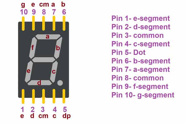
Pin Uses
- Pin 1 is used to give power to the e-segment.
- Pin 2 is used to give power to the d-segment.
- Pin 3 is used to connect the common supply.
- Pin 4 is used to give power to the c-segment.
- Pin 5 is used to give power to the DP LED.
- Pin 6 is used to give power to the b-segment.
- Pin 7 is used to give power to the a-segment.
- Pin 8 is used to connect the common supply.
- Pin 9 is used to give power to the f-segment.
- Pin 10 is used to give power to the g-segment.
Features of the 7-segments Display
- The operating voltage of the 7-segments Display is between 1.5-1.7V DC.
- The operating current of the 7-segments Display is <20mA/segment for a small 7-segments display.
- It is available in different sizes like 9.14mm,14.20mm,20.40mm,38.10mm,57.0mm and 100mm
- It is available in different colors like red, green, blue, white and yellow.
Component needed
- Arduino UNO
- One common cathode or common anode 7-segments display
- 7 resistors of 220 ohms
- Breadboard
- Jumper wires
Pin connections of 7-segments display with Arduino
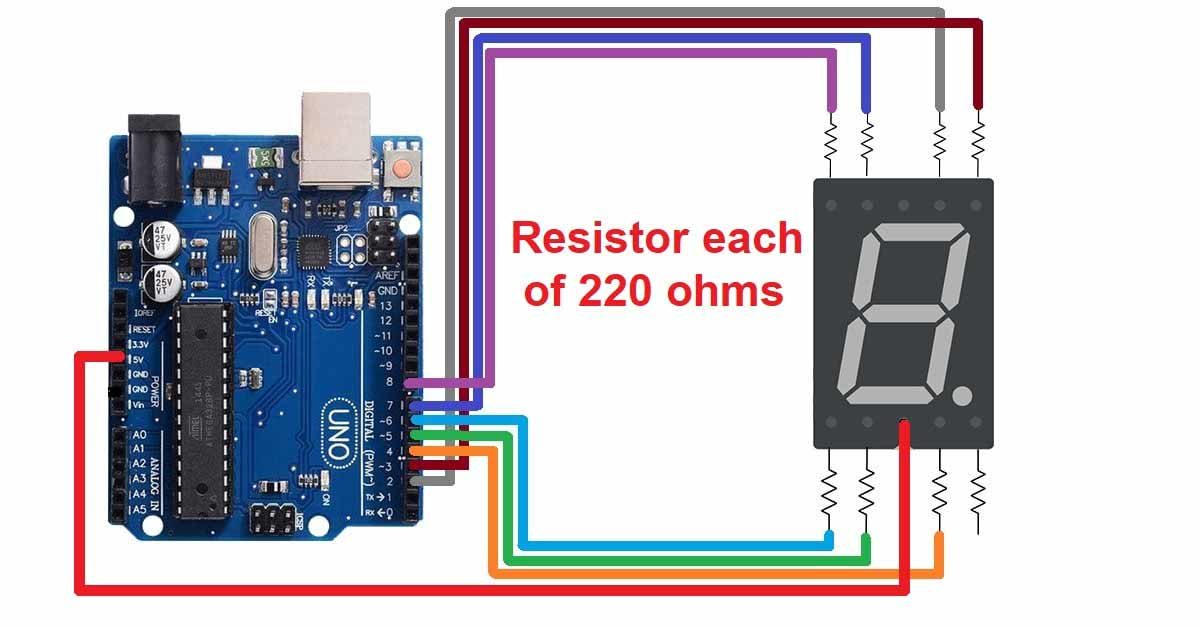
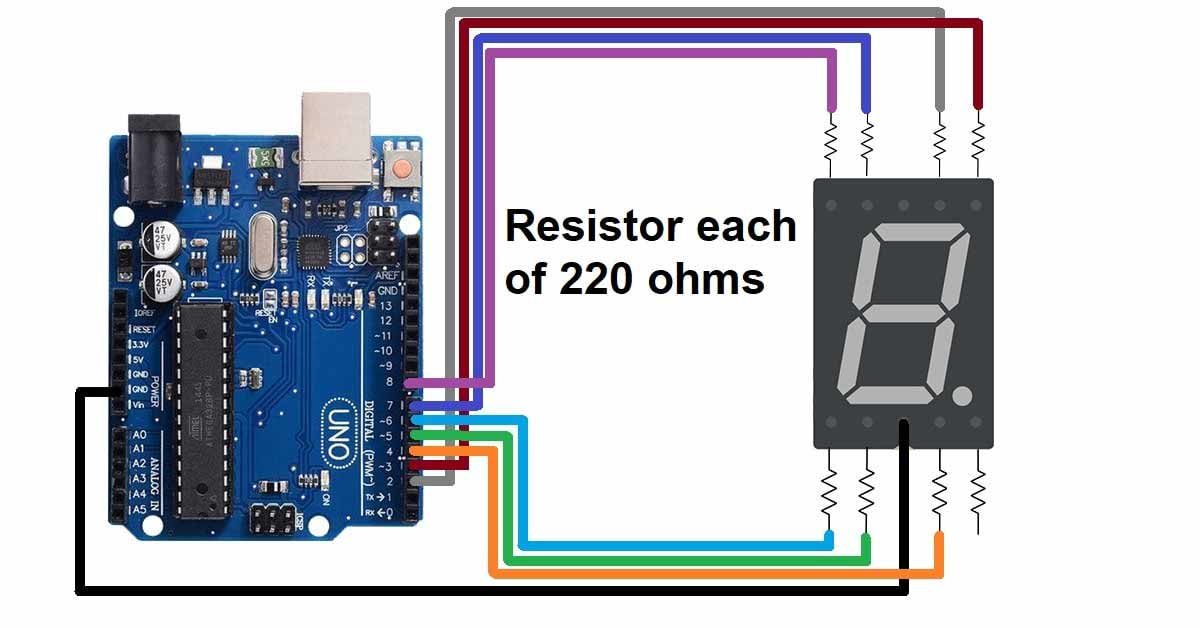
- Connect one 220 ohms resistor to each segment of the display.
- If you are using a common anode display then connect one of the common pins to the 5v pin of the Arduino UNO.
- If you are using a common cathode display then connect one of the common pins to the GND pin of the Arduino UNO.
- Connect the a-segment resistor to the D2 pin of the Arduino UNO.
- Connect the b-segment resistor to the D3 pin of the Arduino UNO.
- Connect the c-segment resistor to the D4 pin of the Arduino UNO.
- Connect the d-segment resistor to the D5 pin of the Arduino UNO.
- Connect the e-segment resistor to the D6 pin of the Arduino UNO.
- Connect the f-segment resistor to the D7 pin of the Arduino UNO.
- Connect the g-segment resistor to the D8 pin of the Arduino UNO.
Circuit diagram of common anode 7-Segments Display with Arduino UNO
Circuit diagram of common cathode 7-Segments Display with Arduino UNO
Arduino code for common anode 7-segments display
//define all the pins of 7 segments

int a=2;

int b=3;

int c=4;

int d=5;

int e=6;

int f=7;

int g=8;


void setup() {

// set all pin as Output

  pinMode(a,OUTPUT);

  pinMode(b,OUTPUT);

  pinMode(c,OUTPUT);

  pinMode(d,OUTPUT);

  pinMode(e,OUTPUT);

  pinMode(f,OUTPUT);

  pinMode(g,OUTPUT);


//Initially turn off all the segments

digitalWrite(a,HIGH);

digitalWrite(b,HIGH);

digitalWrite(c,HIGH);

digitalWrite(d,HIGH);

digitalWrite(f,HIGH);

digitalWrite(e,HIGH);

digitalWrite(g,HIGH);

}


void loop() {


//For displaying 1

digitalWrite(a,HIGH);

digitalWrite(b,LOW);

digitalWrite(c,LOW);

digitalWrite(d,HIGH);

digitalWrite(f,HIGH);

digitalWrite(e,HIGH);

digitalWrite(g,HIGH);

delay(1000);


//For displaying 2

digitalWrite(a,LOW);

digitalWrite(b,LOW);

digitalWrite(c,HIGH);

digitalWrite(d,LOW);

digitalWrite(f,LOW);

digitalWrite(e,HIGH);

digitalWrite(g,LOW);

delay(1000);


//For displaying 3

digitalWrite(a,LOW);

digitalWrite(b,LOW);

digitalWrite(c,LOW);

digitalWrite(d,LOW);

digitalWrite(f,HIGH);

digitalWrite(e,HIGH);

digitalWrite(g,LOW);

delay(1000);


//For displaying 4

digitalWrite(a,HIGH);

digitalWrite(b,LOW);

digitalWrite(c,LOW);

digitalWrite(d,HIGH);

digitalWrite(f,LOW);

digitalWrite(e,HIGH);

digitalWrite(g,LOW);

delay(1000);


//For displaying 5

digitalWrite(a,LOW);

digitalWrite(b,HIGH);

digitalWrite(c,LOW);

digitalWrite(d,LOW);

digitalWrite(f,LOW);

digitalWrite(e,HIGH);

digitalWrite(g,LOW);

delay(1000);


//For displaying 6

digitalWrite(a,LOW);

digitalWrite(b,HIGH);

digitalWrite(c,LOW);

digitalWrite(d,LOW);

digitalWrite(f,LOW);

digitalWrite(e,LOW);

digitalWrite(g,LOW);

delay(1000);


//For displaying 7

digitalWrite(a,LOW);

digitalWrite(b,LOW);

digitalWrite(c,LOW);

digitalWrite(d,HIGH);

digitalWrite(f,HIGH);

digitalWrite(e,HIGH);

digitalWrite(g,HIGH);

delay(1000);


//For displaying 8

digitalWrite(a,LOW);

digitalWrite(b,LOW);

digitalWrite(c,LOW);

digitalWrite(d,LOW);

digitalWrite(f,LOW);

digitalWrite(e,LOW);

digitalWrite(g,LOW);

delay(1000);


//For displaying 9

digitalWrite(a,LOW);

digitalWrite(b,LOW);

digitalWrite(c,LOW);

digitalWrite(d,LOW);

digitalWrite(f,LOW);

digitalWrite(e,HIGH);

digitalWrite(g,LOW);

delay(1000);

}
Arduino code for common cathode 7-segments display
//define all the pins of 7 segments

int a=2;

int b=3;

int c=4;

int d=5;

int e=6;

int f=7;

int g=8;


void setup() {

// set all pin as Output

  pinMode(a,OUTPUT);

  pinMode(b,OUTPUT);

  pinMode(c,OUTPUT);

  pinMode(d,OUTPUT);

  pinMode(e,OUTPUT);

  pinMode(f,OUTPUT);

  pinMode(g,OUTPUT);

}


void loop() {


//For displaying 1

digitalWrite(a,LOW);

digitalWrite(b,HIGH);

digitalWrite(c,HIGH);

digitalWrite(d,LOW);

digitalWrite(f,LOW);

digitalWrite(e,LOW);

digitalWrite(g,LOW);

delay(1000);


//For displaying 2

digitalWrite(a,HIGH);

digitalWrite(b,HIGH);

digitalWrite(c,LOW);

digitalWrite(d,HIGH);

digitalWrite(f,HIGH);

digitalWrite(e,LOW);

digitalWrite(g,HIGH);

delay(1000);


//For displaying 3

digitalWrite(a,HIGH);

digitalWrite(b,HIGH);

digitalWrite(c,HIGH);

digitalWrite(d,HIGH);

digitalWrite(f,LOW);

digitalWrite(e,LOW);

digitalWrite(g,HIGH);

delay(1000);


//For displaying 4

digitalWrite(a,LOW);

digitalWrite(b,HIGH);

digitalWrite(c,HIGH);

digitalWrite(d,LOW);

digitalWrite(f,HIGH);

digitalWrite(e,LOW);

digitalWrite(g,HIGH);

delay(1000);


//For displaying 5

digitalWrite(a,HIGH);

digitalWrite(b,LOW);

digitalWrite(c,HIGH);

digitalWrite(d,HIGH);

digitalWrite(f,HIGH);

digitalWrite(e,LOW);

digitalWrite(g,HIGH);

delay(1000);


//For displaying 6

digitalWrite(a,HIGH);

digitalWrite(b,LOW);

digitalWrite(c,HIGH);

digitalWrite(d,HIGH);

digitalWrite(f,HIGH);

digitalWrite(e,HIGH);

digitalWrite(g,HIGH);

delay(1000);


//For displaying 7

digitalWrite(a,HIGH);

digitalWrite(b,HIGH);

digitalWrite(c,HIGH);

digitalWrite(d,LOW);

digitalWrite(f,LOW);

digitalWrite(e,LOW);

digitalWrite(g,LOW);

delay(1000);


//For displaying 8

digitalWrite(a,HIGH);

digitalWrite(b,HIGH);

digitalWrite(c,HIGH);

digitalWrite(d,HIGH);

digitalWrite(f,HIGH);

digitalWrite(e,HIGH);

digitalWrite(g,HIGH);

delay(1000);


//For displaying 9

digitalWrite(a,HIGH);

digitalWrite(b,HIGH);

digitalWrite(c,HIGH);

digitalWrite(d,HIGH);

digitalWrite(f,HIGH);

digitalWrite(e,LOW);

digitalWrite(g,HIGH);

delay(1000);

}