What is a pulse?
The number of times heartbeats in a minute is called a pulse. The normal pulse rate in humans is 60-100 beats per minute.
How can pulse be measured?
- Heart rate can be monitored in four main ways:
- Electrocardiogram(ECG)
- Photoelectric pulse wave
- Blood pressure monitoring
- Phonocardiography
- Pulse sensors use the photoelectric method
What are pulse sensors?
The pulse sensor is a plug and play heart rate sensor used for real-time heart rate monitoring.
Pulse sensors are broadly of two types:
Transmission type
Pulse sensors that detect the blood flow through light(red or infrared) transmitted/ penetrated through body parts are transmission type sensors. Such sensors are limited to areas where light can easily penetrate e.g. earlobe, finger.
Reflection type
Pulse sensors that detect the blood flow through the light (red, infrared Or green) reflected back onto the sensor are reflection type sensors. Such sensors can be used widely.
Pulse sensors have a wide array of applications such as:
- Healthcare settings
- Sleep Tracking
- Monitoring anxiety
- Fitness bands
- Complex gaming consoles
The applicability of a pulse sensor is enhanced by the following features:
- High sensitivity
- Designed for plug and play
- The small size makes it embeddable into wearables
- Economical measure for heart rate monitoring
How a Pulse Sensor – Heart Rate Detector works?
It is a type of sensor that is used to measure the heartbeats of a person. On the front side of the sensor, an LED and an ambient light sensor are present that is responsible for tracking heartbeats. On the backside of the sensor, an amplification and noise filter is present that is responsible for noise removal and amplification of the pulse signal. The sensor is needed to placed directly above the vein in order to get readings. When you place the sensor on the veins(you can use your fingertip), the LED present on the sensor emits light which then gets reflected from the blood present in the veins. The ambient light sensor will then detect the change in blood flow during heartbeats. And by counting the number of changes that occur per minute we can easily get the pulse rate. Further, from pulse rate data you can easily monitor your sleep and anxiety.
Pin configuration of the Heartbeat sensor
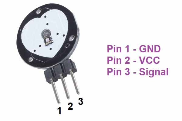
Pin uses
- Pin 1 is the VCC pin used to connect 5 volts.
- Pin 2 is the GND pin used to connect GND.
- Pin 3 is the signal pin used to get data from the sensor.
Features of the Heartbeat sensor
- The operating voltage of the sensor is 3.3-5V DC.
- The current consumption of the sensor is <4mA.
- An inbuilt amplifier and noise filter are present onboard.
Components needed
- Arduino UNO
- Heartbeat sensor
- Breadboard
- Jumper wires
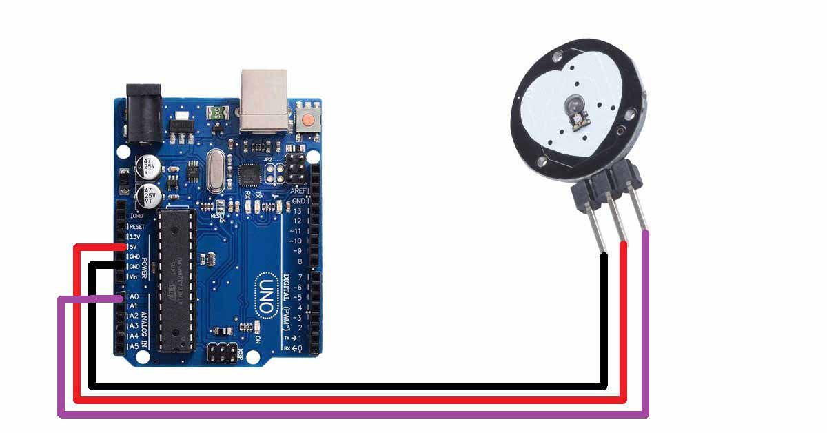
Pin connection of the Heartbeat sensor with Arduino UNO
- Connect the VCC pin to the 5V pin of the Arduino UNO.
- Connect the GND pin to the GND pin of the Arduino UNO.
- Connect the Signal pin to the A0 pin of the Arduino UNO.
Circuit diagram of the Heartbeat sensor with Arduino
Arduino code for the Heartbeat sensor
int sensorPin= A0;
int startTime=0;
int count=0;
int count1=1;
int beat=0;
unsigned int timeS=0;
int hearTbeat=0;
void setup() {
// put your setup code here, to run once:
Serial.begin(9600);
pinMode(2,OUTPUT);
pinMode(sensorPin,INPUT);

}

void loop() {
int sensorData=analogRead(sensorPin);
if(sensorData>512)
{
count=count+1;
beat=beat+1;
delay(100);
if(count1==1)
{
startTime=millis();
count1=count1+1;
}

}
timeS= millis()-startTime;
if((timeS>9500)&(timeS<11500))
{
hearTbeat=count*6;
delay(5000);
startTime=0;
count=0;
timeS=0;
beat=0;
count1=1;

}
Serial.print("Heart Beat:");
Serial.println(hearTbeat);
}