Watch Now……….
What is an IR Sensor?
It consists of an Infra-Red transmitter and receiver and an OpAmp circuit. The IR transmitter consists of an IR LED that emits IR rays. When IR rays hit an object they get reflected back and detected by the IR receiver which is a Photo Diode. The photodiode then converts the captured light into an electrical signal which is further amplified by the operational amplifier and we get logic 1 and 0. The area for the detection of the object can be set by using a potentiometer that is present on the module.
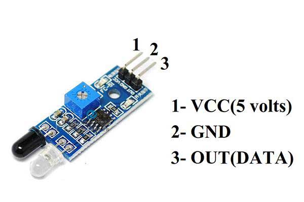
Pin configuration of the IR sensor
Features of the IR sensor
- The input voltage of the IR sensor is 5 volts
- The current consumption of the IR sensor is 20mA
- The range of IR sensor is 0-20cm
Components needed for this project
- IR sensor
- Arduino UNO
- Jumper Wires
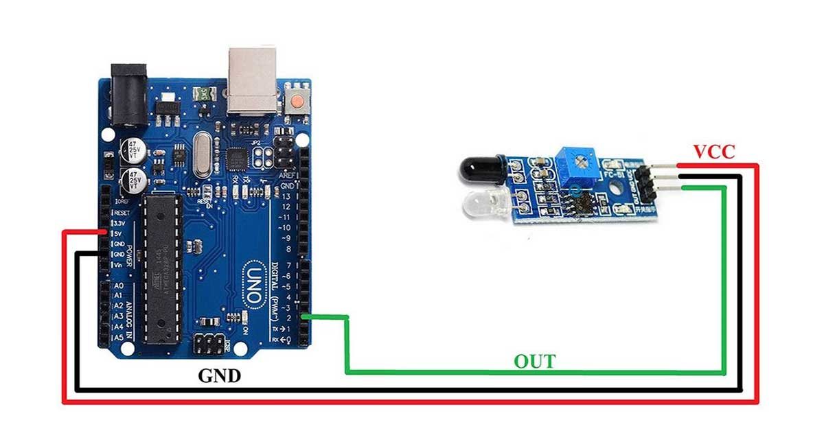
Pin connection of IR sensor with Arduino UNO
- Connect the VCC pin of the IR sensor to the VCC pin of Arduino
- Connect the GND pin of the IR sensor to the GND pin of Arduino
- Connect the OUT pin of IR sensor to the PIN 2 of Arduino
Circuit diagram of IR sensor with Arduino
Arduino code for IR sensor
const int irSensor=2; //define pin where sensor's out pin is connected

void setup() {
  Serial.begin(9600); // set the baud rate for serial communication
pinMode(irSensor,INPUT); //set sensor pin as input to receive data from the pin
}

void loop() {

int irData=digitalRead(irSensor); //create a variable to store sensor data
Serial.print("IR SENSOR DATA:"); //print the data on the serial monitor
Serial.println(irData);
}