Arduino-compatible Seven segments Displays
What is a Seven Segments Display?
7-segment displays are a type of digital display that is commonly used to display numerical information. They consist of seven individual segments that can be lit up to form the numbers 0-9. This simple and cost-effective technology is widely used in a variety of applications, from electronic calculators and digital clocks to digital signage and industrial control systems.
Advantages of 7 Segment Displays
7 segment displays offer several advantages, including:
-
Simplicity: 7-segment displays are simple to understand and use, making them ideal for use in a wide range of applications.
-
Cost-effectiveness: 7-segment displays are relatively inexpensive to produce, making them a cost-effective solution for displaying numerical information.
-
Ease of Use: 7-segment displays are easy to use and program, making them ideal for use in applications where quick and easy updates are required.
-
Durability: 7-segment displays are rugged and durable, making them ideal for use in harsh environments.
| S.No. | Name | Image |
| 1. | 1 Digit 7-segment display | 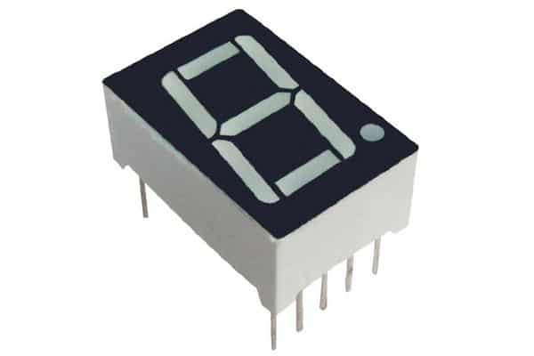 |
| 2. | 2 Digit 7-segment display | 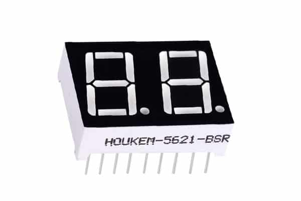 |
| 3. | 3 Digit 7-segment display | 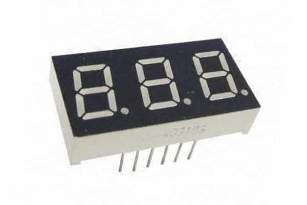 |
| 4. | 4 Digit 7-segment display | 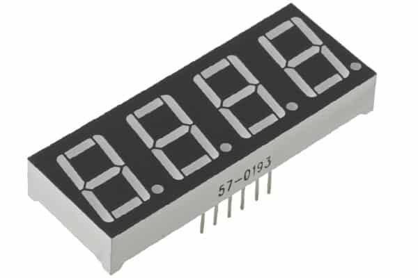 |
| 5. | 4 Digit 7-segement display for clock | 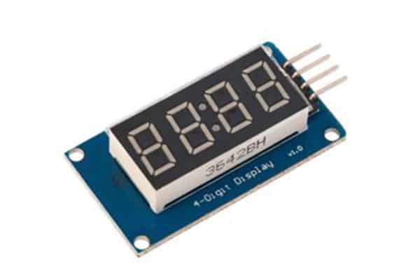 |
| 6. | 6 Digit 7-segment display | 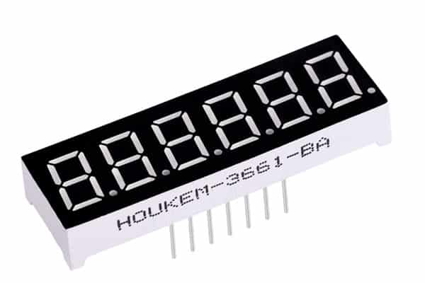 |
| 7. | 8 Digit 7-segment display |  |
Arduino-compatible LED dot matrix
What is a dot matrix?
A dot-matrix display is an electronic device that enables the display of information in a simple alphanumeric or graphic manner in limited-resolution devices or machines e.g. clocks, calculators etc.
Dot-matrix displays are usually created with the following:
- LCD
- OLED
- LED lights
- Thin-Film Transistors (some)
What is a LED dot matrix?
An LED dot matrix or LED display is a low-resolution form of a dot-matrix display created with LEDs. It is made of a 2-D diode matrix with cathodes joined in columns and their anodes joined in rows (or vice versa). Each LED can be individually controlled by controlling the flow of electricity through each row and column pair.
E.g. The 8×8 matrix has 16 pins to achieve a different combination to ON/OFF the LEDs.
LED dot matrix has a wide array of applications such as:
- Industrial and commercial settings to display information (symbols, simple graphics and texts)
- Graph Displays
- Electronic Panel Meters
- Hobby projects and DIYs
- PIXEL gaming
- Designing characters
- Measuring instruments
The applicability of a LED dot matrix is enhanced by the following features:
- Low cost
- Multipurpose
- Easy to Install
- Compact Design
| S.No. | Name | Image |
| 1. | 8X8 LED dot matrix | 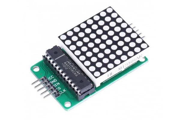 |
| 2. | 8×16 LED dot matrix | 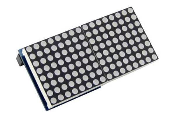 |
| 4. | 8×32 LED dot matrix | 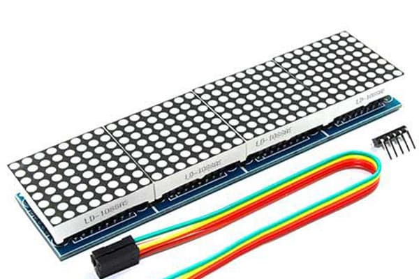 |
Arduino compatible Liquid Crystal Displays(LCDs)
What is an LCD?
LCD stands for liquid-crystal display. LCD is a flat-panel display that uses the light-modulating properties of liquid crystals along with polarizers to display data. Liquid crystals do not emit light directly and use a backlight or reflector that provides light to each pixel that is arranged in a rectangular network to produce images in colour or monochrome.
Each pixel includes a blue, red, and green sub-pixel that can be switched ON/OFF displaying in the following manner:
If all pixels are activated, the display appears white.
If all pixels are deactivated, the display appears black.
If different colour combinations are to be displayed, light levels on each light subpixel need to be changed.
The LCD display is available in different combinations such as 8×2, 8×1, 16×2 etc.
What is a 16×2 LCD?
The 16×2 LCD is a cheap, basic and simple liquid crystal display. It includes:
16 Columns & 2 Rows, therefore displaying 32 characters (16×2=32) in total
Every character is made with 5×8 (40) Pixel Dots
The total pixels within this LCD are 32 x 40 i.e. 1280 pixels.
The 16×2 LCD has a wide array of applications such as:
- CD/DVD players
- Digital watches
- Digital cameras
- Calculators
The applicability of the 16×2 LCD is enhanced by the following features:
- Economic
- Simple
- Compact
- Less power consuming than LEDs
| S. No. | Name | Image |
| 1. | 16×2 LCD | 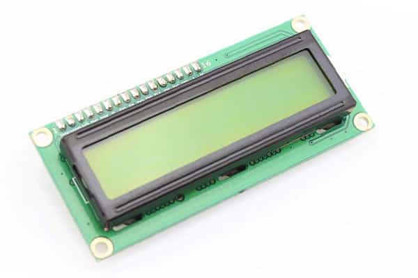 |
| 2. | 20×4 LCD | 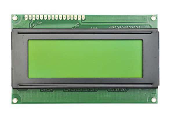 |
Arduino compatible OLED
OLED (Organic Light Emitting Diode) displays are popular for use with Arduino boards due to their high contrast and fast refresh rate. These displays do not require a backlight, as each pixel can emit its own light. This results in a thinner and more energy-efficient display compared to traditional LCDs.
Using OLED displays with an Arduino is relatively simple and straightforward, thanks to the wide variety of libraries and tutorials available. The most common interface used for OLED displays with the Arduino is the I2C (Inter-Integrated Circuit) protocol, which allows multiple OLED displays to be connected to the same two I2C pins on the Arduino board.
To get started with OLED displays and the Arduino, you will need an OLED display module, an Arduino board, and a few jumpers or dupont wires to connect the two. Once you have the hardware ready, you can install the necessary libraries for your OLED display and write your first sketch to display text or graphics on the OLED screen.
| S. No. | Name | Image |
| 1. | 0.91 inch 128×32 OLED | 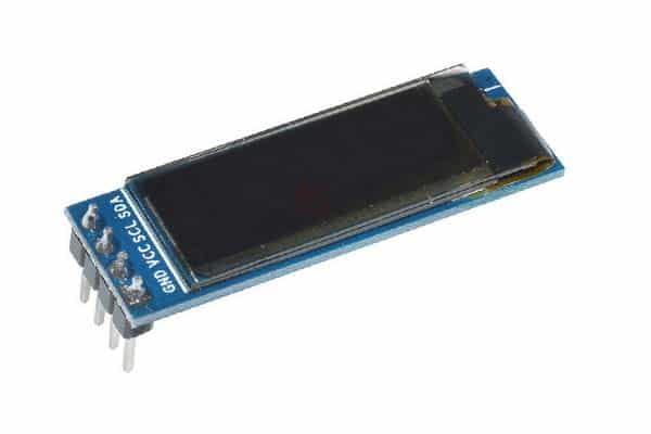 |
| 2. | 0.96 inch 128×64 OLED | 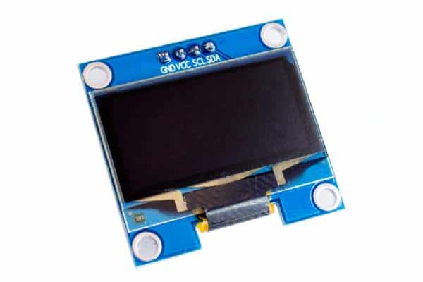 |
| 3. | 1.3 inch 128×64 OLED | 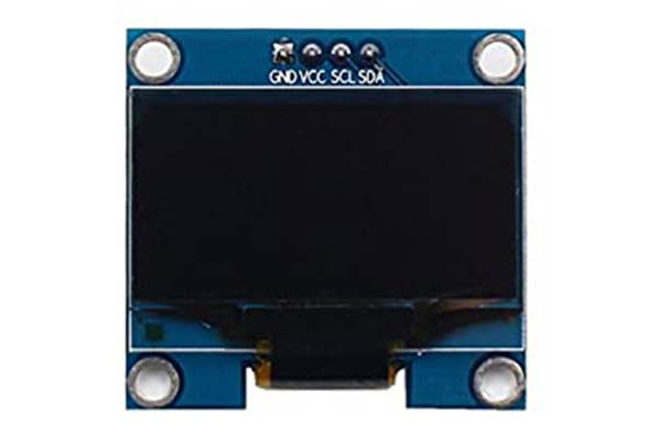 |
Arduino compatible Non-touch TFT LCD
TFT (Thin Film Transistor) displays are popular for use with Arduino boards due to their high resolution and color depth. These displays typically use a TFT panel to control the display of each pixel, resulting in a high-quality image with vivid colors. Non-touch TFT displays do not have a touch screen, making them ideal for projects that do not require touch input.
Using non-touch TFT displays with an Arduino is a straightforward process, with a variety of libraries and tutorials available to help you get started. The most common interface used for TFT displays with the Arduino is the SPI (Serial Peripheral Interface) protocol, which allows high-speed communication between the Arduino and the TFT display.
To get started with a non-touch TFT display and the Arduino, you will need a TFT display module, an Arduino board, and a few jumpers or dupont wires to connect the two. Once you have the hardware ready, you can install the necessary libraries for your TFT display and write your first sketch to display text or graphics on the TFT screen.
| S. No. | Name | Image |
| 1. | 1.8 inch TFT Display | 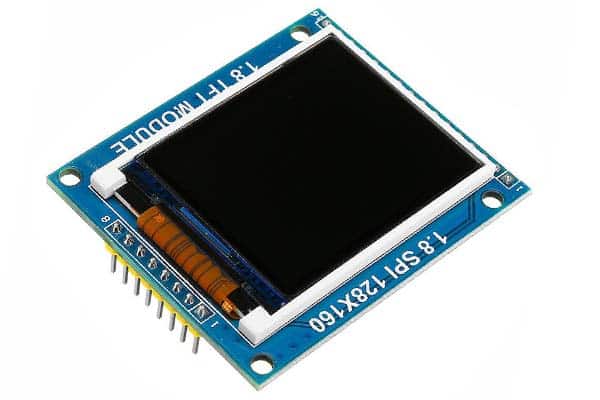 |
| 2. | 2.4 inch TFT Display | 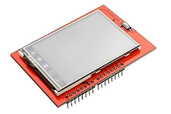 |
| 3. | 2.8 inch TFT Display | 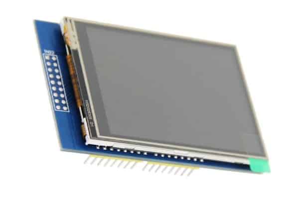 |
| 4. | 3.5 inch TFT Display | 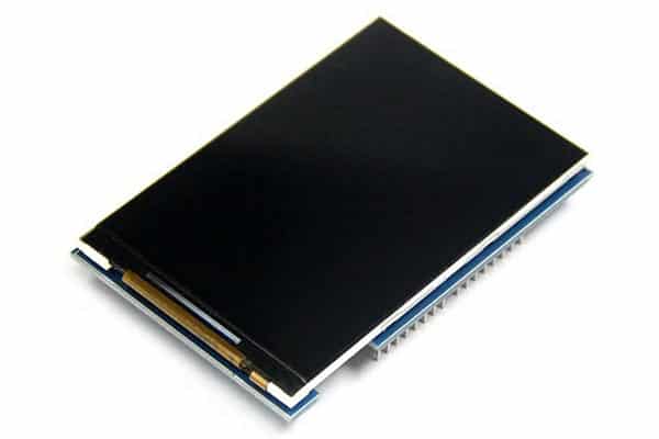 |
Arduino-compatible Touch TFT Display
Touch TFT (Thin Film Transistor) displays are popular for use with Arduino boards due to their high resolution, color depth, and touch input capabilities. These displays typically use a TFT panel to control the display of each pixel, resulting in a high-quality image with vivid colors. Additionally, a touch screen allows for user interaction, making touch TFT displays ideal for projects that require touch input.
Using touch TFT displays with an Arduino is a straightforward process, with a variety of libraries and tutorials available to help you get started. The most common interface used for touch TFT displays with the Arduino is the SPI (Serial Peripheral Interface) protocol, which allows high-speed communication between the Arduino and the TFT display.
| S. No. | Name | Image |
| 1. | 2.4 inch TFT Touch Display | 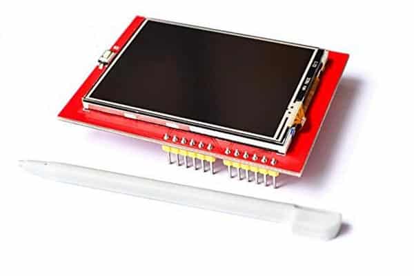 |
| 2. | 2.8 inch TFT Touch Display | 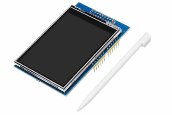 |
| 3. | 3.5 inch TFT Touch Display | 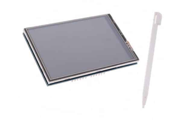 |
Arduino-compatible E-ink Paper Display
E-Ink Paper displays, also known as E-Paper displays, are a type of touch TFT (Thin Film Transistor) display that are popular for use with Arduino boards due to their low power consumption, high visibility in direct sunlight, and touch input capabilities. These displays mimic the appearance of traditional ink on paper, making them ideal for projects that require a low-power, paper-like display.
Using E-Ink Paper displays with an Arduino can be a bit more complex than other types of TFT displays, as there are fewer libraries and tutorials available. However, the interface used for E-Ink Paper displays with the Arduino is typically the SPI (Serial Peripheral Interface) protocol, which allows high-speed communication between the Arduino and the E-Ink Paper display.
| S. No. | Name | Image |
| 1. | 1.54 inch e-ink Paper Display | 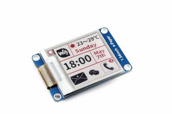 |
| 2. | 2.13 inch e-ink Paper Display | 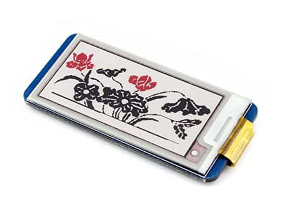 |
| 3. | 2.9 inch e-ink Paper Display | 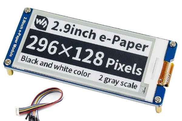 |
| 4. | 4.2 inch e-ink Paper Display | 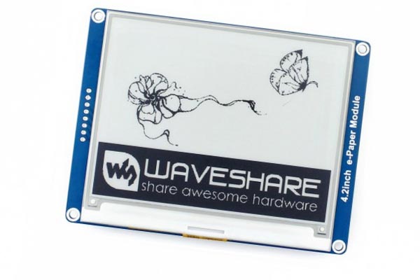 |
| 5. | 7.5 inch e-ink Paper Display | 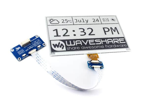 |