What are sensors?
A sensor is a device, module, machine, or subsystem that detects the changes in its environment, produces an output signal and sends the information to other electronics (e.g. a computer processor) for the purpose of sensing a physical phenomenon.
Eg. Tactile sensors, analog sensors, ultrasonic sensors, gas sensors etc.
What is a Reed Switch?
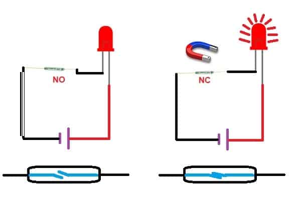
A Reed switch is a type of electrical switch that operates using magnetic fields. It consists of a pair of ferromagnetic metal wires (the reeds) sealed inside a glass or plastic tube. When a magnetic field is applied to the switch, the reeds are drawn together, making contact and completing an electrical circuit.
In Arduino projects, reed switches can be used as input devices to detect the presence or absence of a magnetic field. This makes them useful for detecting the opening or closing of doors, windows, or cabinets, as well as detecting the proximity of magnetic objects.
To use a reed switch with an Arduino board, one of the reed contacts is connected to a digital input pin, while the other is connected to ground. When the magnetic field is applied to the switch, the input pin will detect a change in state from high to low (or vice versa), which can be read by the Arduino software and used to trigger an action.
One important consideration when using reed switches with an Arduino is to ensure that the switch is properly polarized, meaning that the magnetic field is applied in the correct direction for the switch to function. This can be achieved by using a permanent magnet or by placing a polarized diode in series with the switch to protect against accidental reverse voltage.
Working of the Reed switch
Specifications of Reed Switch
- Maximum contact power rating: 10W
- Maximum switching voltage: 300 VDC
- Maximum breakdown voltage: 150 VDC
- Maximum switching current: 0.55 A
- Maximum operating time: 0.45 ms
- Operating temperature: -50°C to +140°C
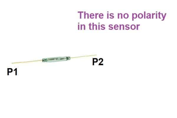
Pin diagram of Reed Switch
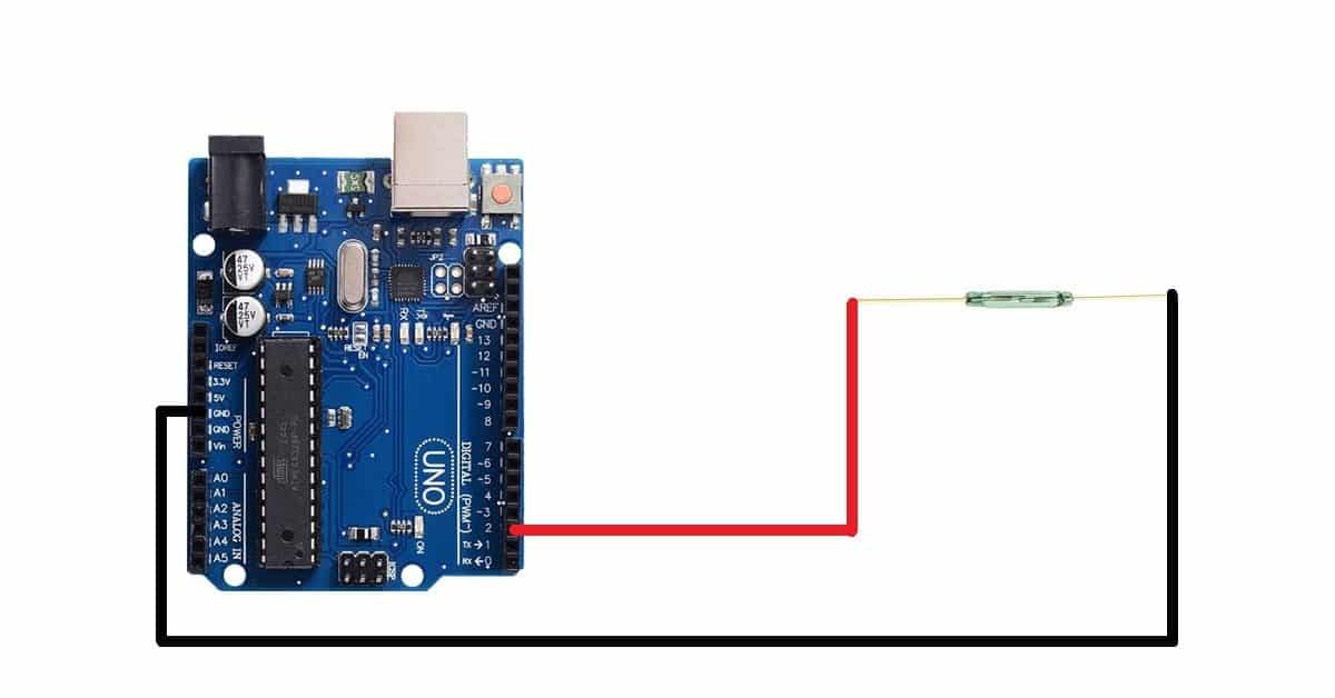
Circuit diagram of Reed switch with Arduino
Pin connection of MQ9 Gas Sensor with Arduino
- Connect the P1 pin of the reed switch to the D2 pin of the Arduino UNO board
- Connect the P2 pin of the reed switch to the GND pin of the Arduino UNO board
Arduino code for interfacing Reed Switch with Arduino
int sensorPin=2;
int sensorData;
void setup()
{
  Serial.begin(9600);
  pinMode(sensorPin,INPUT);
 }
void loop()
{
  sensorData = digitalRead(sensorPin);
  Serial.println("Sensor Data:");

  if(sensorData==LOW)
    Serial.println("Contact");
  else
    Serial.println("No Contact");

  delay(100);
}
Reed switch with Arduino code working
int sensorPin=2;
int sensorData;
Create one variable named sensorPin to store the pin number of the Arduino board pin where you have connected the P1 pin of the sensor. In my case, I have connected the P1 pin of the sensor to the D2 pin of the Arduino UNO board.
Create another variable to store the data received by the Arduino board pin from the reed switch. We will use this variable in the void loop() block.
void setup()
{
  Serial.begin(9600);
  pinMode(sensorPin,INPUT);
 }
Inside the void setup block, set the baud rate for the serial communication and initiate the serial communication using Serial.begin() command.
Then use the pinMode() function to set the sensorPin as INPUT. The Arduino will use this pin to receive the digital data from the sensor.
void loop()
{
  sensorData = digitalRead(sensorPin);
  Serial.print("Sensor Data:");
Inside the void loop() function, use sensorData variable to store the data that is received by the Arduino from the sensor. For this we will use digitalRead() function.
Then, print the data on the serial monitor using the print and println command.
if(sensorData==LOW)
    Serial.println("Contact");
  else
    Serial.println("No Contact");

  delay(100);
}
Now, use the if-else statements to check whether the sensor is working or not. We have connected the P2 terminal of the sensor to the GND pin of the sensor. So, when you bring a magnet near the reed switch, you will get logic LOW from the P1 pin of the reed switch. The same data is read by the Arduino Pin. Logic LOW that ‘0’ will get stored in the variable sensorData.
In the “if” statement we are checking whether the value of sensorData variable is equal to logic LOW or not. If this condition is true the Arduino will print “Contact” on the serial monitor.
If there is no contact then the else statement will run and Arduino will print “No Contact” on the serial monitor.