What is the SIM800L GSM GPRS module?
It is a quad-band GSM/GPRS module. It works on the frequencies GSM850 MHz, EGSM900 MHz, DCS1800 MHz, and PCS1900 MHz. A user can use this module to send and receive phone calls, send and receive messages. It has a built-in audio and microphone driver with the help of which you can easily connect one microphone and speaker to it. When you power it up with a 5-volt 2A power supply, it boots up and automatically searches for a cellular network and connects to it. It has an onboard LED indicator that displays connection status. If it is blinking one time every second then the module is searching for cellular networks. If it blinking after every 3s then the module is connected to a cellular network.
Pin configuration of the SIM800L GSM GPRS module
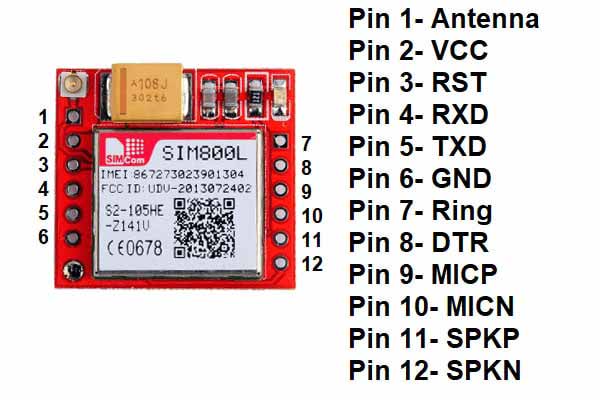
Pin uses
- Pin ANT is used to connect the antenna.
- Pin VCC is used to connect the VCC.
- Pin RST is used to reset the module.
- Pin RXD is used as a receiver pin.
- Pin TXD is used as a transmitter pin.
- Pin GND is used to connect GND.
- Pin Ring outputs logic LOW while receiving calls.
- Pin DTR is used for sleep mode.
- Pin MICP is used to connect the positive terminal of the external microphone.
- Pin MICN is used to connect the negative terminal of the external microphone.
- Pin SPKP is used to connect the positive terminal of the external speaker.
- Pin SPKN is used to connect the negative terminal of the external speaker.
Features of the SIM800L GSM GPRS module
- The operating voltage is between 3.8-4.2 volts.
- The current consumption is 2.0mA in sleep mode, 7.0mA in Idle mode, 350mA for GSM transmission(avg), 2000mA for GSM transmission(peak).
- The operating temperature is between -40°C-85°C.
- It uses UART communication and AT commands.
- It supports 800/900/1800/1900 MHz frequencies.
Components needed
- Arduino UNO
- SIM800L
- One 8 ohm speaker
- One microphone
- The power supply of 5 volts and 2A
- Breadboard
- Jumper wires
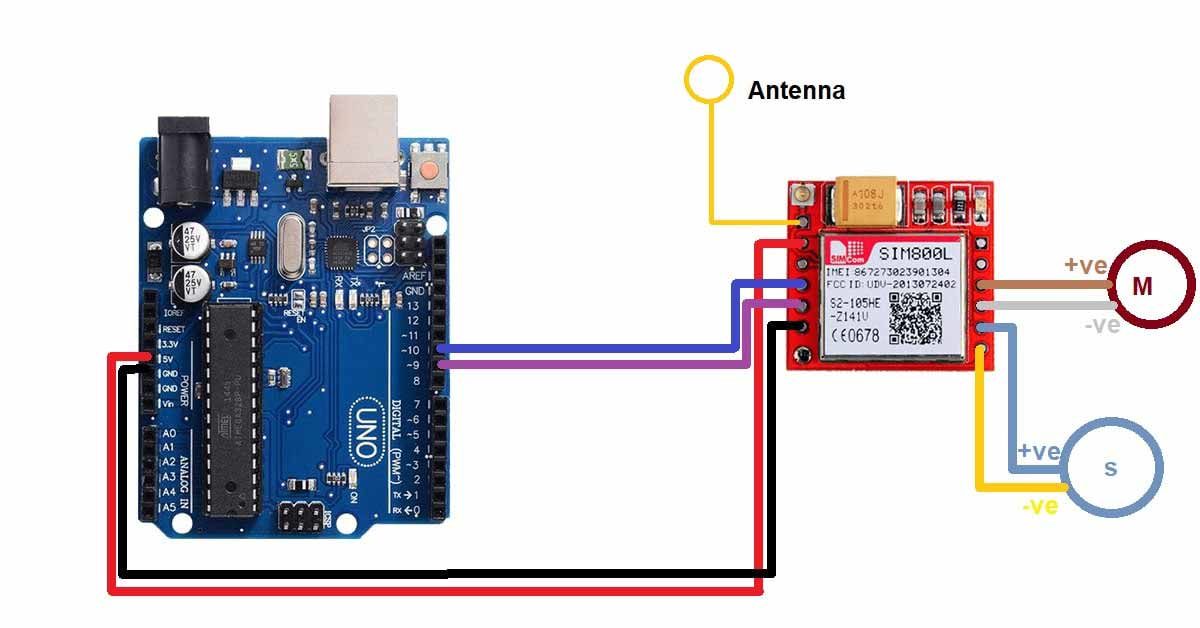
Pin connection of SIM800L GSM GPRS module with Arduino UNO
- Connect an antenna to the Antenna pin.
- Connect the VCC pin of the module to the positive terminal of the external power supply.
- Connect the negative terminal of the external power supply and the GND pin of the Arduino UNO to the GND pin of the module.
- Connect the RXD pin of the module to the D9 pin of Arduino UNO.
- Connect the TXD pin of the module to the D10 pin of the Arduino UNO.
- Connect the MICP pin of the module to the positive terminal of the speaker.
- Connect the MICN pin of the module to the negative terminal of the speaker.
- Connect the SPKP pin of the module to the positive terminal of the speaker.
- Connect the SPKN pin of the module to the negative terminal of the speaker.
Circuit diagram of the SIM800L Circuit diagram of SIM800L with Arduino with Arduino
Arduino code for the SIM800L GSM GPRS module
#include "SoftwareSerial.h"
//Include SoftwareSerial library
SoftwareSerial mySerial(9, 10);
//Define RXD and TXD pin for SIM800L
void setup()
{
  mySerial.begin(9600);//Set baud rate for softwareSerial
  Serial.begin(9600);//Set baud rate for serial communication
  Serial.println("GSM SIM800L BEGIN");
  Serial.println("Enter character for control option:");
  Serial.println("m : to send message");
  Serial.println("c : to make a call");
  Serial.println();
  delay(100);
}

void loop()
{
  if (Serial.available()>0)
//Check if serial communication is available
   switch(Serial.read())
  {
    case 'm':
      SendMessage();
      break;
    case 'c':
      MakeCall();
      break;
  }

}

void SendMessage()
//function to send message
{
  mySerial.println("AT+CMGF=1");
  delay(1000);
  mySerial.println("AT+CMGS=\"+62**********\"\r");
  delay(1000);
  mySerial.println("TYPE MESSAGE HERE");
  delay(100);
   mySerial.println((char)26);
  delay(1000);
}

void MakeCall()
//Function to make a call
{
  mySerial.println("ATD+62**********;");
  Serial.println("Calling");
  delay(1000);
}